

OCA Vacuum Laminator Machine Troubleshooting: Vacuum Level, Seal Leaks and Uneven Pressure
When an OCA vacuum laminator machine begins producing edge bubbles, local haze, alignment drift, or repeated glass damage, changing several settings at once usually hides the cause. A dependable diagnosis starts with the vacuum drawdown curve, the hold-stage behavior, and the exact defect position.
The central question is simple: does the fault come from evacuation, vacuum retention, or uneven mechanical contact? Once that boundary is clear, gasket checks, line isolation, platen inspection, and fixture correction become much more focused.
Start with the Correct Diagnostic Boundary
Large-panel OCA lamination problems often involve several connected conditions. Even so, the first check should separate four branches: vacuum generation, vacuum retention, mechanical contact, and material preparation. That separation prevents a pressure change from masking a leak or a gasket replacement from distracting attention from an unsupported panel.
A vacuum-generation fault appears while air leaves the chamber. The display may move more slowly than an accepted cycle, stop at an unusual point, or vary between identical runs. A retention fault begins after evacuation. The chamber reaches its usual condition but cannot hold it steadily through the selected stage.
Mechanical-contact faults follow a different pattern. The vacuum record may remain stable while one edge, one corner, or one chamber coordinate fails repeatedly. Platen parallelism, fixture stiffness, panel support, connector clearance, and stack height then deserve priority.
Dust, damaged OCA, glass warpage, residue, and unstable alignment can imitate machine faults. Each failed cycle therefore needs both machine data and a defect map.
Evacuation branch
Slow or irregular drawdown points toward the pump path, restrictions, valve opening, blocked ports, or a large open path.
Retention branch
A stable drawdown followed by drift points toward seals, fittings, hose damage, valve bypass, gauge ports, or chamber closure.
Contact branch
Stable vacuum with position-based defects points toward platen balance, fixture support, stack variation, or local interference.
Confirm the machine, fixture, and panel as one assembly
Nominal screen size does not define the real working envelope. The panel, cover glass, fixture border, support plate, cable exit, and loading clearance all occupy space. A connector can also sit outside the visible display outline and change the safe platen area.
For large LCD work, the linked 35-inch platform lists a 600 × 900 mm lamination area and states that the mold should match the actual product. That information defines a starting point, not automatic compatibility for every assembly. A panel near the stated boundary still needs a complete drawing and fixture review.
Before troubleshooting begins, record the exact machine model, fixture code, panel dimensions, glass dimensions, stack thickness, connector position, and loading orientation. These details prevent a normal configuration difference from being mistaken for equipment deterioration.

The machine model, control display, platen, fixture position, and usable assembly envelope should be documented together.
View 35-Inch Laminator DetailsHow to Read an OCA Vacuum Laminator Machine Vacuum Curve
A final vacuum reading shows only one moment. The more useful record is the complete path from chamber closure through evacuation, holding, and venting. Drawdown time shows how air leaves the system, while hold stability shows whether the sealed system can retain the achieved condition.
A phone video can support an initial comparison when the display, timer, chamber state, and sequence remain visible. Keep the camera and load condition consistent.
Record the same landmarks in every cycle
Begin with the machine state. Mark the cycle as cold, warmed, empty, fixture-only, or loaded. Next, record the chamber-close moment, vacuum-start command, repeatable display landmarks, hold-stage start, hold-stage finish, and full vent release.
The record should also show the fixture position and panel arrangement. A wide support plate may cover a port or create narrow air paths. Without that context, a loaded cycle can look like a pump fault even when the restriction comes from the tooling.
- Exact machine model and cycle identification
- Cold, warm, empty, fixture-only, or loaded condition
- Panel structure, dimensions, quantity, and loading position
- Chamber-close and vacuum-start timestamps
- Time to repeatable display landmarks
- Hold-start, mid-hold, and hold-end display values
- Vent timing, unusual sound, vibration, delay, or alarm
- Final defect map and cooled inspection result
Separate slow drawdown from poor holding
Slow drawdown with a stable hold usually directs attention toward flow restriction, incomplete valve opening, a blocked evacuation path, or reduced pump-side performance. The chamber may still seal correctly once it reaches the selected condition.
Normal drawdown followed by rapid loss suggests a larger open path. A displaced gasket, incomplete closure, open vent path, disconnected line, or badly seated fitting becomes more likely. A slow and repeatable drift suggests a smaller leak, valve bypass, gauge-port leak, or temperature-sensitive seal.
Irregular movement deserves a motion check. A hose may leak only while bending, while a valve may respond differently after warming.
Do not treat “-100kPa” as a universal acceptance point
The search phrase “vacuum level -100kPa bonder” can suggest one fixed target. In practice, gauge reference, sensor range, calibration, altitude, display method, and machine design can differ. A single displayed number cannot replace a model-specific specification and an accepted historical curve.
The useful question is whether the same machine reaches and holds its normal condition consistently. A final value can hide slow drawdown, later drift, or restricted flow beneath the fixture.
For a meaningful comparison, run the approved empty chamber, then add the fixture, and finally add a controlled sample. Repeat the comparison at matched machine temperatures. A fault that appears only when loaded belongs to a different branch from one present in every condition.
Trace the Vacuum Leak Path without Random Adjustments
Leak testing should narrow the system in a controlled order. Accessible seals and lines come before internal valves or structural areas.
Safety controls come before service. Stored pneumatic energy and moving platen components require the model-specific isolation procedure. Internal line disconnection or valve service should follow the machine documentation or technical guidance.
Gasket and sealing face
The chamber gasket forms the main perimeter seal. Dust, adhesive residue, glass fragments, cuts, flattening, swelling, twisting, and uneven seating can change hold stability. A thin fiber crossing the contact face may be enough to create an intermittent path.
Inspect the full perimeter under clear light. Corners, joined sections, hinge areas, and closure points deserve close attention. The mating surface matters equally. A sound gasket cannot compensate for residue or damage on the opposite face.
Fittings, hoses, and moving lines
Threaded fittings, push-in connectors, sensor ports, and manifolds create several smaller sealing points. A line entering at an angle can load a connector continuously. Vibration or platen movement may then turn a small weakness into an irregular leak.
Check the entire hose route, not only both ends. Abrasion near frames, flattening beneath covers, hardened sections, sharp bends, heat exposure, and visible collapse can change evacuation. A restricted tube may cause slow drawdown but stable holding, while a puncture may affect both stages.
Valves and sequence response
Evacuation, isolation, and vent valves create different symptoms. An evacuation valve that opens incompletely can slow the curve. An isolation valve with internal bypass can allow gradual return. A vent valve that does not close fully may prevent stable holding from the start.
Control-screen video separates command timing from mechanical response. Record delays, unexpected venting, irregular display movement, and cold-to-warm differences.
Chamber structure and pump path
Chamber seams, viewing windows, feedthroughs, gauge ports, and lid structures belong later in the fault tree. Visible impact, distortion, corrosion, or a changed lid-contact line should be photographed. General adhesive should not be used for structural repair without confirmation.
Pump-side issues often affect evacuation more than retention. Review sound, vibration, inlet restriction, cooling airflow, filters, and model-specific service items only after identifying the installed pump.
A practical isolation order
- Record the approved empty-chamber curve.
- Add the normal fixture and repeat the record.
- Clean and reseat the gasket through the approved method.
- Inspect visible fittings, ports, and moving hose sections.
- Repeat the matched-temperature hold test.
- Isolate only the sections approved for the exact machine.
- Compare chamber retention with pump-side evacuation.
Identify Uneven Pressure across the Platen and Fixture
Once the vacuum curve remains stable, repeated local defects should move the diagnosis toward mechanical contact. Vacuum removes air, but platen movement and fixture support determine how the layers meet. Larger glass makes small height differences more visible.
A displayed pressure value cannot describe local force across the panel. Fixture stiffness, stack height, connector relief, and platen parallelism decide how force reaches the assembly.
Check platen parallelism before increasing force
When one side closes earlier, load concentrates there and pushes air toward the opposite side. Typical evidence includes one-edge bubbles, one-corner damage, repeated pressure shadows, unequal border appearance, or a defect fixed to one machine coordinate.
Measure parallelism through the approved isolated procedure. A visual gap check may reveal a large difference, but adjustment positions should be recorded before correction.
Inspect fixture flatness, stiffness, and support zones
A fixture may look flat on a bench and still deflect under load. It may also rock on the actual platform because of debris, warped layers, or compressed pads. Check the tray on the machine surface rather than treating the fixture as an isolated part.
Support must follow the rear structure. Connectors, frame steps, openings, and flex routes may need relief, while fragile display zones need validated support.
For larger flat-panel work, the large vacuum laminator page provides a relevant equipment route. However, its product page currently shows more than one stage reference. The active configuration, actual usable area, fixture design, and panel clearance should be confirmed together before a purchasing or process decision.

Large-panel planning should confirm the live machine configuration, fixture border, connector clearance, and safe loading path.
Review Large-Panel LaminatorRecord thickness and connector clearance
Stack height changes the closing position and load path. Record the display assembly, cover glass, adhesive, support pad, fixture base, and any approved carrier. A thick frame can contact early while the center remains weak, creating border bubbles or central haze.
Connectors and flex cables can create local high points. A missing or shallow relief pocket may produce a bright mark, crack origin, electrical fault, or alignment shift. Cable routing should appear in both the fixture drawing and the loading photograph.
Increasing total force is not a safe correction for one weak zone. The high areas receive more load first. The correct route is to locate the height difference, verify support, and then review the confirmed process setting.
Use Defect Distribution to Choose the Next Test
A bubble or haze label does not identify the cause. Position, shape, direction, timing, and repeatability provide the useful clues. Before changing settings, photograph the complete panel under front light and side light, then mark the defect on both a panel grid and a machine grid.
Defect fixed to the same chamber coordinate
When different panels fail in the same platen area, the machine or fixture branch becomes stronger. A weak edge, central low-contact zone, repeated debris point, blocked air path, or tilted corner may appear across several loads. A contact map and controlled position swap provide better evidence than another general setting change.
Defect follows panel orientation
When the mark rotates with an approved sacrificial panel, inspect the panel structure, glass shape, adhesive placement, surface condition, and panel-specific fixture reference. Material history also matters. One batch may behave differently even though the machine curve remains unchanged.
Empty cycle passes, loaded cycle fails
This pattern links the fault to the fixture or loaded assembly. The tray may restrict a vacuum port, while a wide panel may narrow the air escape path. Load weight can also affect chamber closure or expose a structural movement that does not appear when empty.
Vacuum remains stable, but one edge keeps failing
Stable retention shifts attention toward border support, platen contact, glass flatness, stack height, cable lift, contamination, or adhesive coverage. One-edge bubbles are not proof of leakage. The edge should be compared with the rear structure and fixture profile before force is increased.
Haze, alignment shift, or breakage
Localized haze may come from poor wet-out, contamination, material damage, or concentrated support. Alignment movement can occur during early contact, platen descent, fixture compression, or venting. A crack requires an immediate stop, fixture quarantine, and safe inspection of the fracture origin.
These failures are not movable residual air. A later bubble-removal stage cannot correct sealed dust, shifted layers, connector interference, or damaged adhesive.
Daily and Weekly Checks That Support Reliable Diagnosis
Routine checks should detect change before a large panel enters the chamber. The checklist should stay short enough for consistent use, yet it must record evidence. A simple “checked” mark cannot explain a later drift in drawdown or repeated edge defect.
Daily pre-operation
- Clean the chamber sealing face and working area
- Confirm gasket seating and visible condition
- Check fixture, platen, and vacuum-port clearance
- Inspect visible hoses, fittings, and moving routes
- Review alarms and unresolved defects
- Record the approved reference cycle
Weekly review
- Compare drawdown and hold trends
- Compare cold and warmed behavior
- Inspect abrasion, connector movement, and valve timing
- Review fixture flatness and support-pad condition
- Check repeated defects by machine coordinate
- Follow model-specific pump and filter service guidance
After gasket, hose, valve, gauge, pump, platen, or fixture work, complete a controlled validation before normal production. Record the replaced component, repeat the empty cycle, and then run an approved sample stack. Compare both vacuum behavior and contact pattern with the accepted reference.
Machine relocation also resets the baseline. Level, utilities, hose routing, chamber closure, fixture seating, and platen behavior should be checked again. A full-size panel should not become the first post-relocation test.
Match the Equipment Route to the Actual Work
A stable machine may still be unsuitable for a changed assembly. Equipment review should begin with the largest panel, complete stack, material, daily quantity, loading method, and installation space.
The three product pages below serve different starting points. Final suitability depends on the live configuration, not a diagonal screen label alone.
For phone and tablet workflows, the vacuum lamination machine page provides the basic bonding route. Plate size and tablet compatibility should still be confirmed for the selected configuration rather than assumed from the product name.
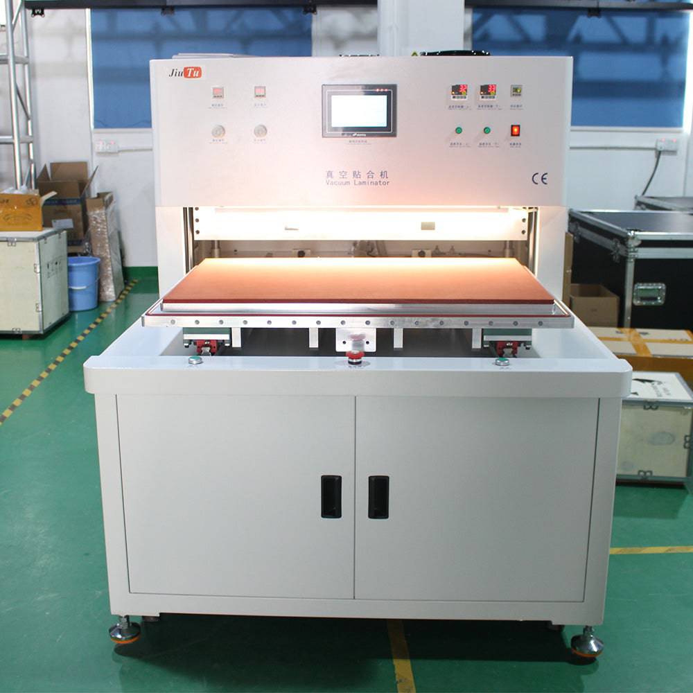
Basic vacuum bonding equipment should be matched through the actual panel size, stack, fixture, material, and output requirement.
View Vacuum Lamination EquipmentPrepare a Complete Troubleshooting Package
A useful technical review connects display behavior with the loaded assembly. Clear evidence prevents unsuitable setting advice.
Machine record
Model, identification plate, installed pump, control version, recent maintenance, replaced parts, relocation history, and fault start date.
Panel and fixture record
Panel and glass dimensions, total stack, adhesive, connector position, flex route, fixture drawing, support zones, and quantity per cycle.
Cycle evidence
Empty, fixture-only, loaded, cold, and warmed videos with a visible display, timer, hold stage, vent response, and unusual sound.
Defect evidence
Full-panel and close photographs under front and side light, chamber position, panel position, rear structure, and cooled inspection.
Include the last accepted cycle and the first failed cycle. Material changes, fixture repairs, cleaning changes, utility work, or different loading quantity may align with the fault. Original records are more useful than values reconstructed after the event.
Finish the package with one precise question. “The empty chamber holds, but the loaded cycle drifts after the fixture enters” directs attention toward the loaded path. “The vacuum curve matches the reference, but the cable-side edge fails” directs attention toward support and local contact.
Frequently Asked Questions
How can a vacuum leak be identified without guessing?
Compare time-based empty, fixture-only, and loaded cycles. Slow drawdown with stable holding usually points toward restriction or pump-side performance. Normal drawdown followed by loss points more strongly toward seals, fittings, hoses, valves, or chamber closure.
What should be checked first when the hold stage becomes unstable?
Start with the accessible sealing path: gasket, mating face, chamber closure, visible hoses, recently serviced fittings, and vent response. Repeat the test at the same machine temperature before moving toward internal valves or structural paths.
Do edge bubbles always mean the chamber is leaking?
No. Border support, adhesive coverage, glass shape, platen contact, contamination, cable lift, and fixture height can create edge bubbles while vacuum remains stable. The defect position and vacuum record from the same cycle should be reviewed together.
How is uneven pressure recognized?
Look for directional or position-based patterns: one-edge bubbles, one-corner breakage, a repeated pressure shadow, or defects fixed to the same chamber coordinate. A controlled contact map and approved panel-position swap provide stronger evidence than increasing total force.
When should the platen and fixture receive a detailed check?
Check them when the vacuum curve is stable but defects repeat by position. A detailed review is also appropriate after breakage, machine relocation, fixture replacement, impact, or a major change in panel structure and loading quantity.
What information should be sent for technical troubleshooting?
Send the machine model, identification plate, panel and glass dimensions, bonded stack, adhesive, fixture drawing, connector position, loading map, pressure and temperature records, full vacuum video, hold duration, gasket and hose photographs, and clear defect images.
Turn the Evidence into a Clear Next Step
A reliable diagnosis connects the vacuum curve, hold stability, sealing path, contact pattern, and defect coordinate. It does not rely on one gauge screenshot or one pressure adjustment. Each controlled comparison should remove one branch from the fault tree.
Before another production cycle, record an empty, fixture-only, and loaded test. Map the visible defect against both panel and chamber coordinates. Then submit the machine model, complete stack, fixture, cycle videos, maintenance history, and clear photographs for review.
- Confirm whether the fault begins during drawdown, holding, or mechanical contact.
- Correct local support or sealing evidence before increasing pressure.
- Match the equipment route through actual panel dimensions, material, daily quantity, and fixture needs.
A complete project file supports a more accurate assessment of the existing process and the required OCA vacuum laminator machine configuration. It also helps separate a service problem from a fixture redesign or equipment-capacity decision.