

Sheet-to-Sheet Laminator for Glass and LCD Work
A glass panel can look clean on the bench at 9:00. After bonding, however, one corner bubble, one faint pressure mark, or one small alignment shift may suddenly appear under side light. That is the part many teams underestimate in sheet-to-sheet work. A Sheet-to-Sheet Laminator is not only a pressing machine. It is a controlled way to support glass, guide the landing path, reduce trapped air, and make LCD bonding more repeatable.
The real value does not come from a single impressive parameter. It comes from the quiet details: how the lower glass sits, how the upper layer lands, how air escapes, how OCA or OCR behaves, and how the result is checked after the panel rests for 20 minutes. Those details decide whether the panel becomes a finished display or another rework job.
This guide follows a practical route: see the defect, understand the cause, judge the working scene, then choose the bonding setup. The goal is not to make the process sound complicated. The goal is to make glass LCD lamination easier to control in daily work.
Sheet-to-Sheet Laminator Basics: The Real Problem Is Control
In hand bonding, a small film can still be adjusted before it fully lands. With glass-to-LCD work, that room disappears quickly. Once two rigid layers touch at the wrong angle, air has fewer ways to escape.
Therefore, sheet-to-sheet lamination should not be treated as a simple press. The lower layer needs stable support. The upper layer needs a predictable landing path. Meanwhile, the adhesive needs enough time and space to flow without trapping dust or air.
A common scene explains it well. A 15.6-inch industrial LCD sits on the fixture. The center looks flat, but the cable side is slightly raised. When pressure comes down, the machine cannot guess that one corner is sitting higher. It only follows the setup given to it.
That is why the most useful question is not “How much pressure can the machine apply?” A better question is “Can the panel stay supported, aligned, and clean during the few seconds when the two sheets meet?”
Why manual placement starts to fail on larger panels
Manual placement still works for some small and forgiving screens. However, larger glass behaves differently. One hand supports the left side, the other hand supports the right side, and the middle can still sag slightly.
Also, larger panels make tiny shifts easier to see. A 0.5 mm drift may not look serious during loading, but it can become obvious along a black printed border after the LCD turns on. The defect feels worse because the eye naturally follows long straight borders.
For this reason, a large area lamination station is useful when the work repeats. It reduces random hand movement and keeps the process closer to the same result each time. That repeatability is often more valuable than a single impressive setting.
Process judgment: If bubbles, corner shift, or pressure marks appear in the same position across several panels, the issue is probably not random. Start with support, landing path, adhesive handling, and inspection habits before changing pressure.
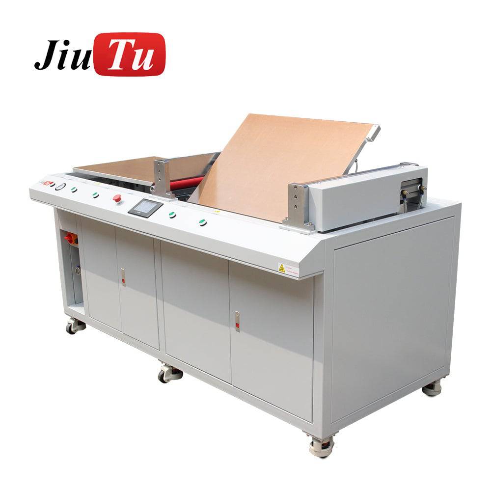 View Laminating Machine For Glass
Glass Support and Fixtures: The Bottom Layer Decides the Result
A glass panel feels firm when held by hand. However, it may still flex when placed over a hollow area. That small movement is easy to miss before bonding, yet it can leave a pressure mark after lamination.
Therefore, the fixture should not only hold the outline. It should support the real pressure path. The middle area, cable side, raised frame, black border, and corners all need attention before sample bonding begins.
A simple test works well. Place the panel on the fixture, then press gently near each corner with one finger. If the panel rocks, the fixture is not ready. If the center dips, the support surface needs adjustment.
A fixture should follow the real panel, not only the size label
Two panels can both be 15.6 inches and still behave differently. One may have a cable tail on the short side. Another may have a raised metal frame. A third may have a printed border with a small height step.
Because of this, the real sample is more useful than a size name. A drawing helps, but the physical stack shows where support is missing. If the fixture supports the wrong area, the laminator only presses that mistake more evenly.
For repeated work, a custom fixture often saves time after the first setup. The loading position becomes familiar. The panel sits the same way at 10:00, 13:00, and 17:00. The process feels less dependent on one skilled person’s hand feeling.
How to judge whether a custom fixture is needed
A custom fixture becomes worth considering when the same display appears often, when the visible border is narrow, or when one corner keeps failing. It is also useful when the panel has a raised frame or cable exit that needs a safe channel.
For example, if three out of ten panels show a bubble on the same long edge, the reason is probably mechanical. It may be support height, edge pressure, adhesive size, or an air path that closes too early.
In that case, increasing pressure is not the first move. Checking fixture flatness is more useful. A stable fixture lets the adhesive spread naturally instead of forcing the LCD stack into stress.
Fixture checklist before sample bonding
- Measure the real glass size, LCD outer size, and active display area.
- Check whether the panel rocks at any corner before adhesive is exposed.
- Confirm cable tail clearance, especially near the short edge.
- Look for worn pads, screw holes, dust on fixture edges, and uneven support points.
- Use a rejected panel for the first fixture test when possible.
- Record fixture version, pad material, loading direction, and repeated defect position.
This checklist is not complicated. Still, it catches the problems that usually cost the most time. A panel rarely fails because the fixture was checked too carefully.
Landing Path and Alignment: Pressure Cannot Fix Bad Placement
The first few seconds of landing matter more than many settings on the screen. If the top glass lands diagonally, pressure cannot correct the position. It only locks the mistake inside the stack.
A good landing path looks calm. The top layer lowers straight. Air escapes from a planned direction. The lower sheet stays quiet on the fixture. Then pressure finishes the bond instead of forcing two sheets together.
This is where a Sheet-to-Sheet Laminator becomes useful for repeat work. It creates a steadier path for glass LCD lamination, especially when the panel is large, narrow-bordered, or hard to hold by hand.
When CCD alignment is worth considering
CCD alignment is not needed for every panel. A wide-border display with forgiving tolerance may work with a solid fixture and clear reference marks. However, CCD support becomes useful when the visible window is narrow or the display has camera holes, sensor windows, or strict edge alignment.
Automotive displays are a good example. A tiny diagonal shift can look obvious across a long center screen. Kiosk displays can show the same issue near printed borders. In these cases, hand alignment may pass one sample but fail to stay stable across a full day.
Still, CCD is not magic. It needs clean reference points and a fixture that prevents sliding after positioning. The camera can show where the glass should land, but the mechanical support must keep it there.
 View CCD Vacuum Laminating Machine
Why pressure should not be the first adjustment
When an edge looks weak, increasing pressure feels like the fastest answer. However, that can create new trouble. Too much pressure may squeeze adhesive, mark a soft LCD area, or stress a thin glass corner.
Before changing pressure, check whether the vacuum level was stable. Then check the fixture, the air exit path, and the way the upper sheet landed. If the defect changes after a slower loading test, the problem was probably not pressure.
This small habit avoids wasted time. It also keeps the process from becoming a guessing game where every failed sample leads to another random number change.
Bubbles, Dust, and Adhesive Choice: Read the Defect Before Changing the Machine
A bubble usually has a history. It may start as a dust point, trapped air, weak vacuum timing, uneven support, or a small adhesive cut problem near the edge. The difficult part is that the cause often hides until the panel is inspected under the right light.
Dust is especially annoying. One speck can look harmless before pressing. After lamination, it can become a bright dot with a tiny ring around it. On a black screen, the same dot may look worse than expected.
Therefore, clean handling matters even when the room is not a formal cleanroom. Dust-free wipes, gloves, covered trays, ionizing air, and shorter peel-to-place movement all help. The goal is simple: keep random particles away from the adhesive moment.
Center bubbles and edge bubbles tell different stories
Center bubbles often point to dust, weak vacuum, fast pressure timing, or surface preparation. Edge bubbles usually point somewhere else. They may come from border height, glass shape, adhesive size, fixture interference, or an air path that closed too early.
For example, a bubble line along one long side may suggest uneven support. A corner bubble may suggest trapped air during first contact. Small bubbles near a printed black border may suggest height difference around the ink layer.
A useful habit is to photograph every failed sample under the same light angle. Then mark the defect area: center, long side, short side, corner, cable side, or black border. After 10 samples, the pattern usually becomes clear.
OCA and OCR should follow the panel structure
OCA film suits many flat and repeatable bonding jobs. It gives a controlled adhesive thickness and a cleaner handling route when storage, peeling, and placement are handled well.
OCR liquid adhesive can help with some irregular gaps or larger optical structures. However, it adds dispensing, overflow control, flow judgment, curing, and cleanup. It may solve one problem while creating another if the workflow is not ready.
So adhesive choice should not come from habit. It should come from panel shape, air gap, cover glass thickness, border design, and daily output rhythm.
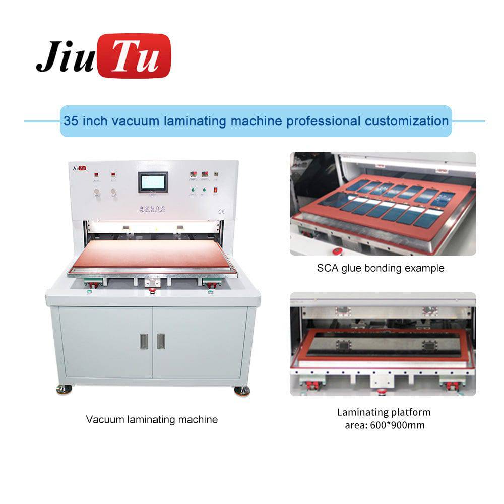 View OCA Laminator Machine
Bubble removal should support a good first bond
Bubble removal can help with small residual bubbles after OCA bonding. However, it should not become a rescue plan for every poor first bond. Large trapped bubbles usually mean the first stage needs attention.
If micro-bubbles disappear after bubble removal but edge bubbles remain, the issue may still be fixture support or adhesive size. If no bubbles improve, the cycle, adhesive, or lamination stage needs review.
QC Inspection After Lamination: Look Twice, Under Different Light
A fresh bonded panel can look clean under the first overhead lamp. However, some defects appear only under side light, a grey screen, or after the adhesive settles for a short time.
For this reason, inspection should not be a quick glance. A practical routine includes white, black, and grey screens. Then the panel should be tilted slowly under side light. After 15–30 minutes, the edge should be checked again.
Grey screen inspection is especially useful. White can hide pressure marks. Black can hide slight haze. Grey often shows uneven support, small dents, and local stress more clearly.
QC should guide the next process change
Defect photos are process evidence. A repeated center mark may point toward support. Random bright dots may point toward dust handling. A repeated corner bubble may point toward landing path or air release.
Also, only one major setting should change during the next test. If pressure, temperature, vacuum time, fixture pad, and loading method all change together, the result becomes hard to read.
Post-lamination QC checklist
- Check white, black, and grey screens before final judgment.
- Move the panel slowly under side light to find edge bubbles.
- Inspect the cable side and raised frame area carefully.
- Let the bonded panel rest for 15–30 minutes before the second check.
- Record defect position, fixture version, adhesive type, and bubble removal cycle.
- Change one main process variable at a time during the next test.
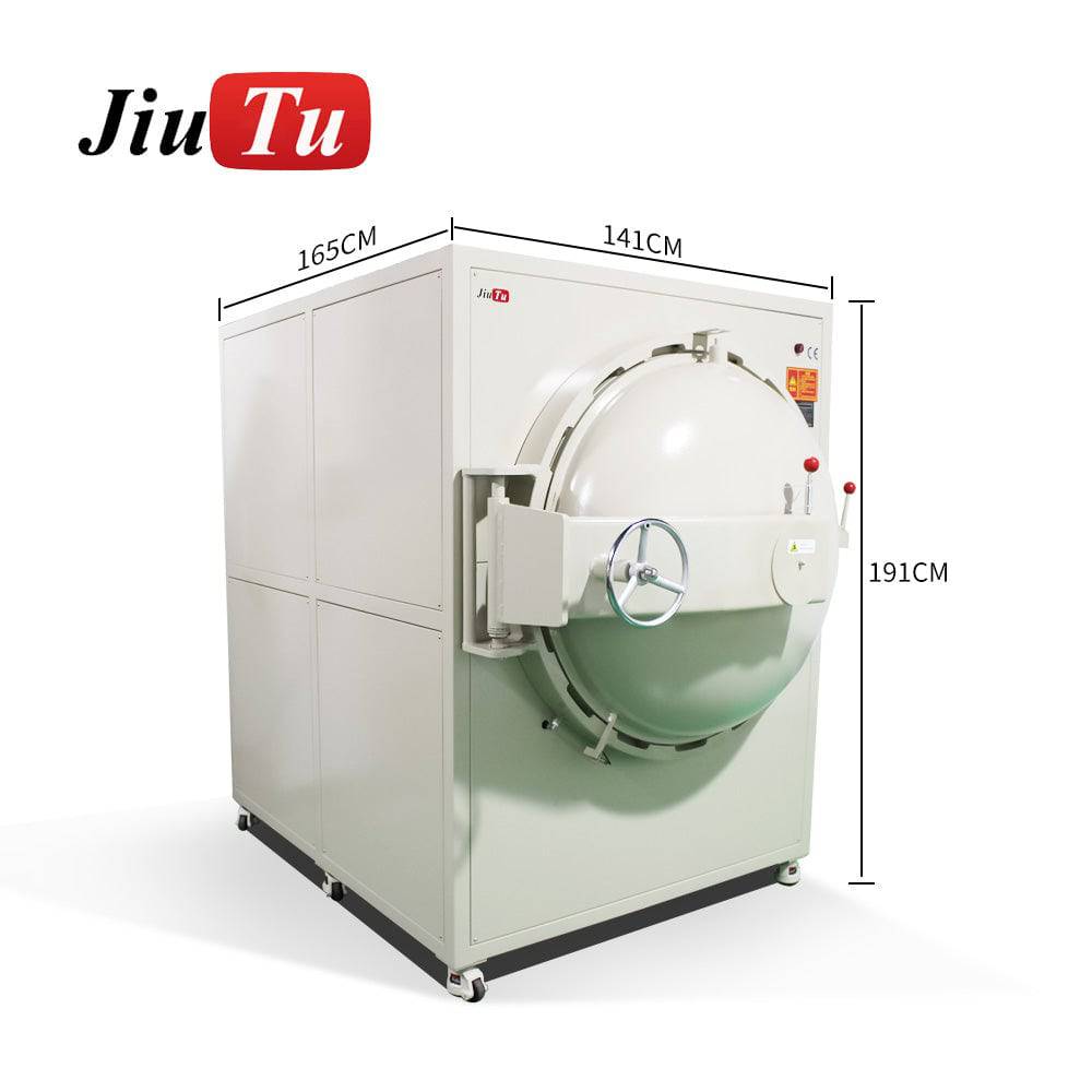 View LCD Bubble Remover
Setup Selection: Match the Hardest Regular Panel, Not the Easiest Sample
The easiest sample can create false confidence. A small clean panel with a wide border may pass on many stable setups. The harder regular panel tells the truth.
That panel may be a large LCD, a narrow-border cover glass, a curved automotive screen, or a module with a cable tail near one corner. If it appears often and fails in a repeated way, it should guide the setup choice.
A suitable process discussion should include panel size, glass thickness, LCD structure, adhesive type, daily quantity, fixture need, defect photos, and whether post-bonding bubble removal is required.
When a larger working area makes sense
A larger working area helps when the panel approaches the platform edge. It also helps when fixture walls, cable clearance, or safe loading movement need more space. However, a larger area does not fix poor support by itself.
The working area gives room. The fixture gives stability. Both matter. A wide platform can still fail if the center support is hollow or the panel lifts near the cable side.
When a full optical bonding workflow is better
Some work needs more than one station. A laminator handles the main bond. A bubble remover handles small residual bubbles. Inspection lights confirm the result. Clean handling tools protect the adhesive between steps.
Therefore, the better question is not which machine looks strongest. The better question is which steps create stable output. A Sheet-to-Sheet Laminator should fit the full optical bonding route, not only one pressing moment.
For equipment direction, JiutuStore carries optical bonding, OCA lamination, LCD repair, and bubble removal equipment. The practical next step is to match the setup to the actual panel stack, defect photos, adhesive route, and daily workflow.
Before choosing a setup, prepare these details
A clear sample description saves time. Panel size, glass thickness, adhesive type, daily quantity, cable position, fixture requirement, and defect photos are more useful than a general machine name.
- Panel outer size and active display area
- Cover glass thickness and LCD structure
- OCA or OCR process preference
- Repeated defect photos under side light
- Daily quantity and current loading method
Extended Reading: Build a Stronger Optical Bonding Content Path
Sheet-to-sheet bonding works best when it connects with related process topics. Cleanroom handling, OCA lamination, CCD alignment, bubble removal, and QC inspection all support the same final goal: a cleaner display result with fewer repeated defects.
Clean handling before bonding
Dust control starts before the machine closes. Shorter peel time, covered trays, and steady loading habits reduce visible dots.
OCA process planning
OCA bonding depends on adhesive storage, film peeling, fixture support, vacuum timing, and bubble removal after lamination.
QC-driven improvement
Defect photos should guide the next test. Repeated corner, edge, and center issues usually point to different causes.
FAQ: Sheet-to-Sheet Laminator Process Questions
What makes a Sheet-to-Sheet Laminator different from manual glass placement?
A Sheet-to-Sheet Laminator controls support, landing path, vacuum timing, and pressure more consistently than hand placement. Manual work may pass small panels, but larger rigid glass and LCD stacks need a steadier process to reduce trapped air, drift, and pressure marks.
Why do edge bubbles appear even when the center looks clean?
Edge bubbles often come from border height, uneven support, adhesive size, cable-side lifting, or an air path that closes too early. The center may look clean because the main pressure area is stable, while one edge still has a support or landing problem.
When is CCD alignment useful for glass LCD lamination?
CCD alignment is useful when the display has narrow borders, camera holes, sensor windows, long visible areas, or repeated alignment drift. It is especially helpful when different operators get different placement results. A stable fixture is still required.
Should OCA or OCR be selected for large glass LCD bonding?
OCA works well for many flat and repeatable stacks because adhesive thickness is controlled. OCR may help with irregular gaps or certain large optical structures, but it adds dispensing, curing, overflow control, and cleaning work. The panel structure should decide the route.
What details help Jiutu match a suitable setup?
Useful details include panel size, glass thickness, LCD structure, adhesive type, daily quantity, cable position, fixture needs, and clear defect photos. A short loading video can also help when bubbles or alignment shift repeat.
Final Takeaway: Let the Panel Decide the Setup
Sheet-to-sheet lamination is not about pressing harder. It is about letting two rigid layers meet in a controlled way. The fixture supports the glass. The landing path protects alignment. The adhesive needs a clean and steady moment. QC then shows whether the process is truly stable.
For real selection, the best starting point is the actual panel, not a machine name. Send Jiutu the panel size, glass thickness, adhesive type, daily quantity, fixture situation, and defect photos. With those details, the setup can be matched around the work itself instead of guessing from parameters.
Explore Optical Bonding Machine Setups