A stable optical bonding display build removes the air gap that drives glare and haze. As a result, contrast looks deeper and text appears sharper in bright environments. At the same time, bubbles and dust become more visible under grazing light. For that reason, bubble-free OCA lamination depends on repeatable gates, not a single machine setting.
In real production, the goal is simple: stable clarity, stable edges, and stable yield. However, small process drift can turn into large cosmetic defects. For example, a minor leak-rate change can weaken vacuum stability. Likewise, a small platen flatness issue can create pressure gradients that trap air.
What optical bonding changes
Optical bonding replaces an air layer with optically clear adhesive between surfaces. Consequently, internal reflections drop and black levels look stronger under bright light. In addition, the image appears closer to the cover lens, improving perceived sharpness. Still, this clarity makes tiny defects stand out quickly.
Mechanical behavior shifts after bonding as well. Because layers act as one structure, vibration causes less micro-movement at interfaces. Meanwhile, repeated tapping feels more stable because the stack flexes less. However, edges become more critical because stress concentrates near borders.
Why bubbles matter beyond appearance
A bubble is more than a visual flaw. For instance, voids scatter light and reduce local contrast around the defect. Additionally, trapped air can concentrate stress and amplify corner risk. Over time, edge bubbles can evolve into edge lift during thermal cycling.
Micro-bubbles deserve special attention. Initially, tiny voids may hide under normal room lighting. Later, they can grow after heat exposure or a rest period. Therefore, conditioning and debubbling must work as a system.
Benefits and best-fit scenarios
Sunlight readability is a common driver for bonding. Because reflections reduce, a module stays legible under high ambient light. Moreover, glare reduction can support lower backlight power in outdoor conditions. As a result, bonding fits kiosks, marine interfaces, and vehicle dashboards.
Industrial environments gain different benefits. Under vibration, a bonded stack resists micro-shifts between layers. Meanwhile, touch response often feels more direct without an air gap. Also, bonding can reduce dust pumping from temperature swings.
Medical and lab equipment often values uniformity. Since the stack is more integrated, wipe-down routines stay consistent over time. Additionally, optical uniformity improves readability under bright clinical lighting. Therefore, bonding fits devices where clarity is functional, not decorative.
Refurbishment lines also benefit from structured lamination. In that setting, defect gates prevent rework loops and shorten cycle time. Likewise, clear inspection criteria reduce late-stage uncertainty. Consequently, a disciplined approach often improves throughput without aggressive tuning.
OCA film vs. LOCA selection logic
OCA film provides repeatable thickness and predictable optical behavior. As a result, alignment and flatness control become easier to standardize. In addition, film avoids many liquid-flow artifacts seen with liquid adhesives. However, film can trap air during first contact if peel and tacking move too fast.
LOCA can fill uneven gaps and suit variable spacing structures. In direct terms, LOCA needs a cure step, often UV. That cure step adds time and introduces cure-related risks, such as shrink marks or haze. Moreover, overflow can become a permanent cosmetic defect.
A practical selection approach starts with geometry. Flat, predictable stacks often favor film for repeatability and yield. Complex shapes may favor LOCA when cure control is strong. Either way, process gates and inspection drive bubble-free results more than adhesive marketing.
Bubble-free OCA lamination workflow (defect gates)
Bubble-free lamination works best as a chain of defect gates. Each gate blocks a defect class before it becomes permanent. Additionally, each gate should have a measurable pass/fail rule. As a result, yield improves predictably and troubleshooting becomes faster.
The workflow below uses short steps with clear intent. Moreover, each gate ends with a “Common mistake” and “Quick check.” This structure keeps training consistent across shifts. Therefore, the line stays stable even with mixed panel sizes.
Gate 1: Environment control and stability targets
Stable temperature and humidity reduce adhesive variability and moisture-driven micro-bubbles. Many facilities start around 22–26°C and 40–55% RH as a baseline. However, stability matters more than a perfect number. For example, a useful target is tight daily drift, such as keeping RH swings small across shifts.
Static control belongs in this gate as well. Grounded benches, ESD mats, and ionizing airflow reduce dust attraction during peel and transfer. Meanwhile, covered staging limits recontamination after cleaning. As a result, upstream cleanliness becomes repeatable.
Common mistake: a stable setpoint with large daily swings from HVAC cycles.
Quick check: defect rates rise at the same time each day.
Gate 2: Cleaning and pre-bond inspection
Cleaning must remove oils and residues without adding lint. Consequently, wipe material, wipe direction, and solvent control matter. Meanwhile, circular wiping often redeposits particles, so consistent linear passes perform better. Also, ionizing airflow after cleaning reduces static attraction during handling.
Inspection should occur before adhesive contact. Grazing light reveals smears and haze, while backlight reveals particles and internal defects. Moreover, consistent lighting across shifts improves decision consistency. Therefore, inspection is part of yield control, not an optional habit.
Common mistake: harder scrubbing that creates lint and micro-scratches.
Quick check: haze appears under tilt, even when the surface seems clean.
Gate 3: Film preparation and liner peel control
Liner peel is a frequent source of trapped air and static. A slow peel reduces charge generation and keeps film flatter. In contrast, abrupt peel can create curl that tents the film. For that reason, peel speed and peel angle should be standardized.
Edges deserve extra protection. Because edges see stress and humidity first, edge contamination becomes edge bubbles later. Additionally, oils from handling can migrate under pressure. Consequently, controlled tools and protected staging reduce repeat edge failures.
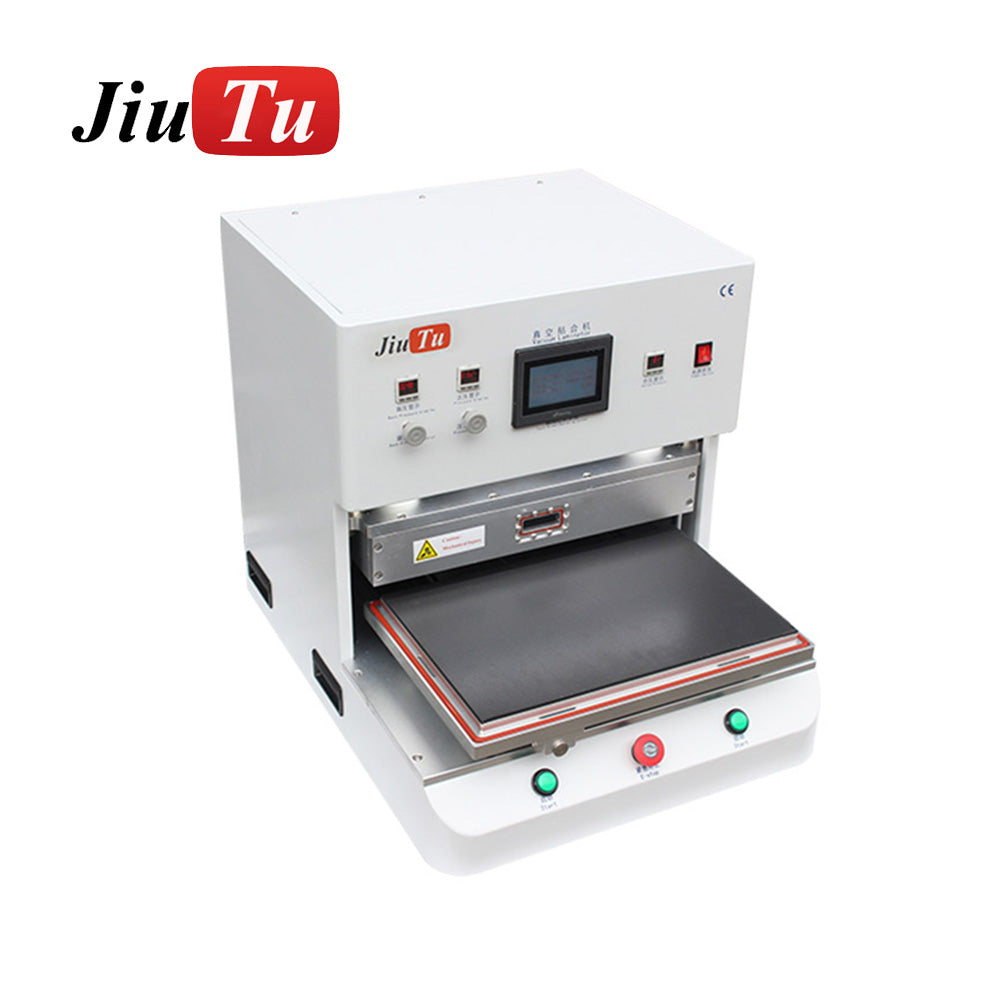
Film placement support improves repeatability when handling drives variation. For example, a thermal film laminating machine supports controlled OCA or polarizer placement. As a result, wrinkles and handling marks reduce before vacuum lamination begins.

Common mistake: fast peel followed by immediate bonding without re-ionizing.
Quick check: dust appears after peel, even when cleaning looked stable.
Gate 4: Alignment strategy and first-contact control
Alignment controls air escape paths, not only position. If first contact starts at a corner, air can be sealed with no exit route. Conversely, guided contact from a controlled start line lets air move out. Therefore, the tack plan should be defined and repeatable.
Fixture design influences first contact. A rigid support reduces panel bow and improves pressure distribution. Meanwhile, consistent tack pressure avoids stress lines that later become lift lines. As a result, fixture quality often matters as much as vacuum time.
Common mistake: repeated lift and re-tack to chase alignment, trapping air each time.
Quick check: bubbles repeat near the same tack point across panels.
Gate 5: Vacuum lamination (primary bubble prevention)
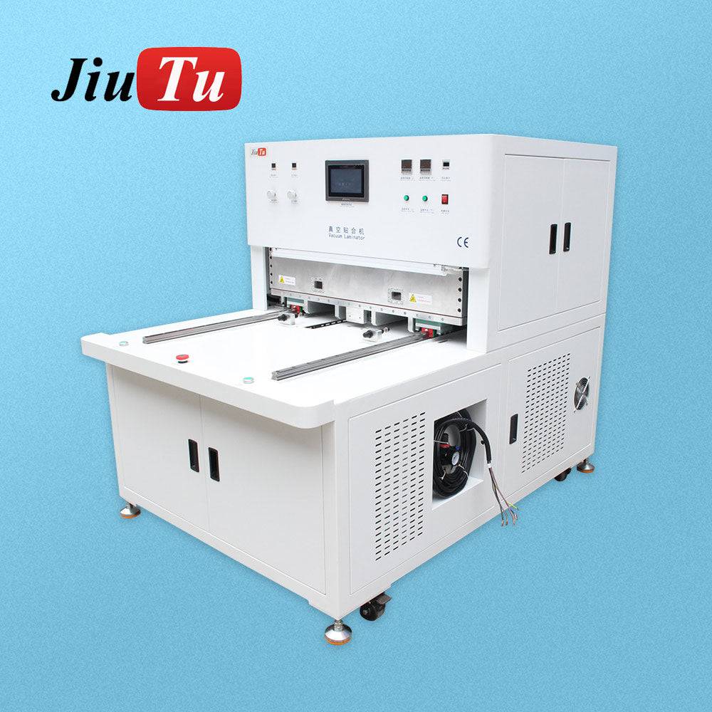
Vacuum lamination prevents bubbles by removing air before pressure seals layers together. Consequently, macro bubbles become far less likely than open-air pressing. Meanwhile, a smooth pressure ramp reduces corner trapping and channel sealing. Therefore, ramp profile often matters as much as peak pressure.
Vacuum level and dwell time depend on chamber sealing, panel size, and stack geometry. Notably, effective vacuum depends on equipment specifications, leak-rate behavior, and evacuation paths. In addition, platen flatness and temperature mapping influence pressure uniformity at contact. As a result, stable patterns matter more than copying a single number.
In practical recipes, vacuum extraction, controlled heating, and ramp timing work together. Moreover, longer evacuation often helps larger panels with long escape paths. Still, cycle speed should follow verified stability, not assumptions. For deeper product details on extraction sequence and application scenarios, this vacuum laminator page supports the same logic: CG+OCA vacuum laminating machine working principle and use cases.
Common mistake: shorter vacuum dwell to raise throughput, then relying on debubbling to rescue.
Quick check: corner bubbles rise first, then micro-bubbles spread later.
Gate 6: Edge control, sealing, and stabilization
Edges are the first failure point in many bonded stacks. Because edges see stress, humidity, and handling, weak edges show quickly. Meanwhile, edge sealing can block moisture ingress and stabilize adhesion. Therefore, edge steps should be treated as reliability steps, not cosmetic finishing.
A short stabilization step can reduce late surprises. For example, controlled rest allows stress relaxation and reduces outgassing spikes. Also, careful stacking avoids point loads that distort the bond line. Consequently, handling between lamination and debubbling can change defect rates.
Common mistake: stacking panels on uneven supports, creating local pressure marks.
Quick check: lift lines appear after storage, despite clean initial inspection.
Gate 7: Debubbling (finishing micro-void removal)
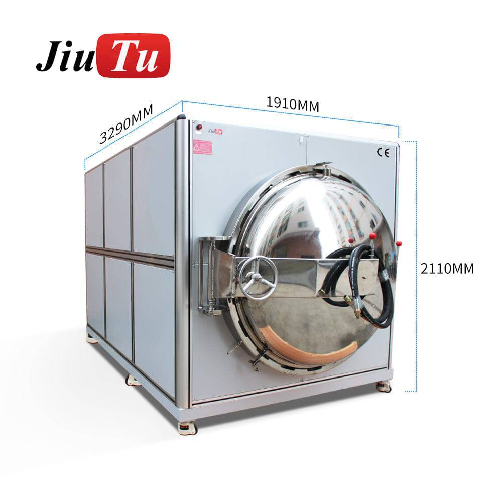
Debubbling collapses micro-bubbles that survive vacuum lamination. Autoclave-style bubble removal applies controlled pressure, often with moderate heat. Meanwhile, this step improves uniformity on larger panels where micro-voids persist. Therefore, debubbling should be planned as a finishing stage, not an emergency fix.
Debubbling recipes should match materials and stack thickness. Higher pressure and heat are not always better, because stress and coating risks rise. Moreover, moisture-driven bubbles can reappear if storage and staging remain uncontrolled. For a deeper explanation of why pressure and heat work, this internal guide fits as a follow-up read: How screen bubble remover machine works.
Common mistake: forcing high heat to collapse bubbles, then creating haze or edge stress.
Quick check: bubbles collapse, yet haze bands increase under grazing light.
Materials & handling SOP (hard rules)
A handling SOP reduces variation more than many parameter changes. In practice, consistent staging prevents moisture pickup and limits particle exposure. Moreover, a predictable peel and transfer routine reduces static spikes. Therefore, a concise SOP should be treated as process equipment.
OCA film benefits from controlled acclimation. When film moves from cold storage to use too quickly, tack and stiffness shift. Additionally, condensation risk rises when humidity is high. As a result, acclimation time should be defined and logged.
Staging discipline protects cleaning work. Once a surface is cleaned, open-air time becomes a risk multiplier. Meanwhile, airflow and foot traffic can add particles in minutes. For that reason, covered staging and tray rules matter as much as wiping.
Mini checklist (6–8 hard rules)
-
Max open-air time: set an upper limit between cleaning and first contact.
For example, short windows reduce recontamination and stabilize white-spot rates. -
Fixed sequence: peel → ionize → first contact, with no shortcuts.
This order reduces static pull-in right before bonding starts. -
Glove discipline: use clean gloves and replace on a defined schedule.
Oils migrate fast, especially near edges and corners. -
Edge tools only: handle edges with dedicated tools, not bare fingers.
Edge oils and dust often become edge bubble chains later. -
Tray and cover rule: always cover staged parts between gates.
Covered trays reduce drift when queues build up. -
Film acclimation rule: wait until film temperature stabilizes near room conditions.
Stable temperature reduces curl and improves predictable tacking behavior. -
No mixed stacks: avoid mixing cleaned and uncleaned parts in one tray.
Cross-contamination is subtle and difficult to diagnose later. -
Document exposure events: log any long stops or line interruptions.
Exposure logs explain late bubbles that appear after a rest period.
These rules look simple, yet they raise yield quickly. Additionally, they reduce random drift between shifts. As a result, tuning becomes more meaningful and less chaotic.
Parameter thinking and tuning map
Parameter tuning works best when it follows physics, not habit. First, air must be removed before pressure seals escape paths. Next, contact must be controlled so corners do not trap air. Finally, micro-voids can be finished under controlled pressure and heat. Consequently, a tuning map prevents endless trial-and-error loops.
Room stability should be treated as a process variable. Even moderate RH shifts change static behavior and moisture uptake. Meanwhile, temperature changes alter adhesive tack and flow subtly. For that reason, logs should include RH, temperature, and film acclimation time.
Vacuum settings should be framed with context, not promises. Deep vacuum often helps, yet effective vacuum depends on equipment specs and leak-rate behavior. Additionally, evacuation paths depend on panel size and edge geometry. As a result, vacuum stability matters more than headline vacuum value.
Parameter tuning map (small table, high value)
| Defect pattern | Adjustment priority | First check, then action |
|---|---|---|
| Corner bubbles after lamination | Contact and ramp | verify tack plan, then slow ramp profile |
| Center bubbles on larger panels | Support and dwell | check fixture support, then increase evacuation time |
| Random micro-bubbles everywhere | Handling and environment | check peel static, then tighten staging discipline |
| Bubbles appear after rest period | Moisture and conditioning | verify RH drift, then extend acclimation control |
| Newton ring patterns | Flatness then thickness | check platen flatness/pressure, then review adhesive thickness |
Newton ring issues often look material-driven at first glance. However, flatness and pressure distribution should be checked first. After those checks, adhesive thickness makes sense to review. Therefore, the sequence prevents wasted changes.
Practical starting ranges without over-promising
Many lines begin with conservative cycles and stable room conditions. Vacuum dwell often starts in a few-minutes range on smaller panels, then increases with size. Meanwhile, pressure ramps usually start gentle, then tighten after bubble patterns stabilize. Additionally, debubbling often begins moderate, then adjusts based on micro-bubble persistence.
Because products vary, a tuning approach is more useful than fixed numbers. Stable yield should be verified across multiple panels and lots. Moreover, leak-rate checks should be part of periodic verification. For a deeper selection-and-acceptance view focused on vacuum stability and platen flatness, this internal guide matches the same mindset: How to buy the right one (no mistakes) – adhesive bonding machine.
Acceptance criteria and inspection
Acceptance criteria prevent late-stage debate and stabilize yield reporting. Moreover, clear criteria support consistent training across shifts. Therefore, inspection should be standardized by lighting, angle, and distance.
Optical acceptance (visual)
Active area clarity is the main requirement in most builds. Under defined grazing-light inspection, no visible bubbles should appear in the viewing zone. Meanwhile, backlight inspection should show no particle-driven bright points. Also, haze bands and streaks should be treated as defects when clarity is the goal.
Edge zones often need separate criteria. Some builds allow minor edge voids outside the viewing zone. However, edge void chains often predict future lift under humidity. For that reason, edge criteria should reflect reliability goals, not convenience.
Reliability acceptance (edge and seal)
Edges should be inspected for lift lines and bubble chains. Seal continuity should be verified where sealing is specified. Meanwhile, corners should be checked for chips and stress whitening. As a result, small edge issues can be stopped before they grow.
Functional acceptance (touch and uniformity)
Touch response should remain consistent across the bonded area. Display uniformity should not show local blotches caused by voids or pressure marks. Additionally, mechanical feel should not show soft spots that indicate uneven adhesion. Therefore, functional checks complete the picture when optical appearance alone is insufficient.
A consistent inspection flow improves speed. Start with grazing light for haze and streaks. Then use backlight for particles and internal voids. Finally, verify edges with a controlled tilt. Consequently, repeatable inspection reduces false rejects and missed defects.
Troubleshooting matrix (symptom → cause → action)
Troubleshooting becomes faster when symptoms map to causes. Additionally, repeatable patterns often point to fixture or contact issues. Meanwhile, random patterns often point to contamination or static. Therefore, the matrix below supports faster root-cause isolation.
| Symptom | Likely root cause | Practical action |
|---|---|---|
| Bubble chain along one edge | edge contamination, weak edge pressure, moisture ingress | tighten edge handling, verify sealing consistency, check pressure uniformity |
| Bubbles clustered near one corner | first contact seals air, ramp too fast, corner support mismatch | change contact start line, smooth ramp, verify corner support |
| Random micro-bubbles after peel | static attracts dust, peel routine inconsistent | slow peel, re-ionize after peel, strengthen covered staging |
| White bright points under backlight | particles sealed in bond line | improve pre-bond inspection, cover parts, tighten wipe control |
| Haze bands or streaks | residue smear, film wrinkle, uneven pressure | refine cleaning method, control film flatness, verify pressure mapping |
| Newton ring interference | flatness mismatch, pressure non-uniformity, thickness mismatch | check flatness/pressure first, then review adhesive thickness |
| Bubbles appear hours later | moisture/outgassing, incomplete conditioning, storage exposure | stabilize RH, extend acclimation, tighten packaging SOP |
| Center bubbles on larger panels | panel bow, insufficient evacuation, weak support | improve fixture support, increase dwell, verify platen flatness |
This matrix supports prioritization. It reduces the urge to change multiple variables at once. Additionally, it keeps tuning aligned with defect physics. As a result, improvements are easier to confirm and sustain.
More defect examples and prevention solutions fit naturally as a follow-up, especially when building training materials: Most common OCA bonding defects and prevention solutions.
Equipment pairing and line layout
A stable line assigns one job per station. Consequently, each step blocks a defect class before it becomes permanent. Meanwhile, the core pairing usually includes film handling, vacuum lamination, and debubbling. Therefore, equipment selection should follow the workflow, not the other way around.
For a practical selection hub that covers vacuum lamination and bubble control by panel size, this collection works well: Optical bonding machine options for different panel sizes. It supports comparing formats without jumping across unrelated categories. As a result, a coherent line layout becomes easier to plan.
Line balance matters as well. If lamination runs faster than debubbling, queues grow and contamination risk rises. Meanwhile, long waits after cleaning reduce yield even with strong machines. Therefore, planning should include buffers, covers, and inspection stations.
Core pairing for repeatable yield
-
Film placement support and alignment fixtures for repeatable first contact
-
Vacuum laminator matched to panel size, leak-rate stability, and platen flatness
-
Bubble remover sized to throughput and stack thickness for finishing micro-voids
-
Inspection lighting and anti-static tools to protect upstream gates
This pairing forms a prevention-plus-finishing system. It also keeps troubleshooting simple because each station has a clear job. Consequently, root-cause work becomes faster and less opinion-driven.
Large-format considerations
Large panels amplify everything. Dust risk rises because area increases. Flatness problems become visible because optical uniformity is unforgiving. Pressure distribution must remain stable to avoid center bubbles and patterned haze. Therefore, rigid plates and stable fixtures matter more as size grows.
Rework & separation (decision rules)
Rework capability protects yield, yet it must be controlled carefully. If rework is uncontrolled, scratches and coating damage can exceed recovery value. Therefore, rework should have clear entry criteria and clear exit criteria.
Separation methods vary by stack and coating type. Some builds allow controlled heat separation with proper tooling. Meanwhile, other builds require specialized separation approaches to avoid polarizer damage. Additionally, adhesive removal must avoid residue that later causes haze. Consequently, rework steps should be gated like production.
Rework decision rules (simple and strict)
-
Viewing zone defects: treat as scrap in most lines.
A visible defect in the main area rarely becomes stable after rework. -
Edge zone isolated bubble: allow rework when edges remain mechanically stable.
Isolated edge voids can be recoverable with controlled re-lamination. -
Bubble chain near corners: rework only after root cause is confirmed.
Otherwise, the same chain often returns after thermal cycling. -
Max rework loops: set a low limit, such as one or two loops.
Additional loops increase scratch risk and reduce coating stability.
These rules reduce inconsistent decisions. They also protect time by preventing endless rescue attempts. As a result, yield improves without adding hidden quality risk.
Rework cleanliness must match production cleanliness. After separation, surfaces often carry adhesive residue and micro debris. Meanwhile, aggressive scraping can add micro scratches that become visible later. Therefore, gentle removal and strict inspection remain essential.
Two short field cases
Case 1: 10.1-inch industrial HMI panel
A 10.1-inch panel often shows corner bubbles when first contact starts at a corner edge. In practice, a controlled contact start line and smoother ramp reduce that pattern. Meanwhile, random bright points often trace back to static during liner peel. As a result, ionizing after peel can reduce defects faster than pressure changes.
Because the panel is smaller, evacuation paths are shorter. Consequently, vacuum dwell tuning converges quickly once contact control stabilizes. Also, covered staging after cleaning prevents recontamination during queue time. Therefore, gate discipline often produces larger gains than speed chasing.
Case 2: 15.6-inch control panel display
A 15.6-inch panel magnifies flatness and support issues. Slight panel bow can trap air near the center even with good vacuum. Moreover, pressure non-uniformity can create patterned haze bands under grazing light. Therefore, fixture support and platen flatness become primary variables.
Late-appearing micro-bubbles are common in this size class. In that situation, moisture and outgassing are frequent causes, especially with uncontrolled staging. Meanwhile, debubbling can finish micro-voids, yet it cannot fix weak edges. Consequently, conditioning and edge control should be stabilized first.
FAQ
What makes bonded stacks look clearer under sunlight?
First, reduced internal reflection improves contrast in high ambient light.
Additionally, the image appears closer to the cover surface.
Why do bubbles appear after a rest period?
Often, moisture or outgassing expands micro-voids after time and heat.
Meanwhile, uncontrolled staging can add moisture to films and liners.
What causes repeating edge bubble chains?
Typically, edge contamination and uneven edge pressure drive chain patterns.
Also, weak sealing can allow humidity to enter the border.
When does debubbling become essential?
Generally, micro-void risk rises with panel size and stack complexity.
Therefore, debubbling becomes a finishing requirement on larger builds.
How should Newton ring patterns be handled?
First, check platen flatness and pressure uniformity across the bonding area.
Then, review adhesive thickness only after geometry checks are complete.
What reduces static-driven dust defects most reliably?
In practice, grounding and ionizing airflow reduce charge attraction.
Meanwhile, slower peel routines reduce charge generation at the source.
Why do haze bands show instead of discrete bubbles?
Often, residue smears, film wrinkles, or uneven pressure create banded haze.
Additionally, repeated lift and re-tack can imprint stress patterns.
How can acceptance criteria reduce debate across shifts?
Define inspection lighting, angle, distance, and the viewing zone boundary.
Then, separate edge-zone rules from active-area rules clearly.
What keeps rework from damaging panels?
Strict entry rules and low rework-loop limits protect coatings and surfaces.
Moreover, controlled separation avoids micro-scratches and residue haze.
What equipment pairing stays stable for mixed panel sizes?
Typically, film handling plus vacuum lamination plus debubbling forms the core.
Meanwhile, strong fixtures and inspection protect upstream defect gates.
Related reading
-
Full OCA bonding production line setup guide for LCD and touch panels
-
LCD laminating machine guide: cleaner, bubble-free OCA lamination
Conclusion and actionable next steps
Bubble-free bonding comes from prevention gates, stable vacuum behavior, and controlled finishing. Moreover, handling discipline often outperforms aggressive parameter changes. When acceptance criteria and decision rules stay clear, yield improves predictably. For that reason, an optical bonding display process can scale without becoming fragile.
Actionable next steps:
-
Standardize the SOP hard rules, especially open-air limits and peel sequencing.
-
Stabilize vacuum behavior by tracking leak-rate, platen flatness, and ramp repeatability.
-
Lock rework decision rules and max loops, then audit compliance weekly.
Finally, consistent execution keeps an optical bonding display result clear, durable, and repeatable across lots.