On an LCD/OLED rework line, the harshest “inspection light” is often the backlight. A panel can look clean on the bench, then a single bright edge line appears the moment the backlight turns on. The usual culprit isn’t mysterious—air, timing, and pressure distribution are simply unforgiving at optical interfaces. That’s why a vacuum laminating machine matters: it turns lamination from a hand-feel craft into a controlled cycle that can be repeated shift after shift.
This article stays strictly on one topic: how a vacuum laminating machine is used for LCD/OLED lamination and refurbishment (especially OCA-based bonding), what specs actually move yield, how pricing really works, and how to choose and accept a machine with measurable tests—without getting trapped by brochure language.
Principle: What a Vacuum Laminating Machine Really Does in LCD/OLED Lamination
A good lamination outcome is not “press harder.” It’s remove air paths, manage contact timing, and lock thickness uniformity before the adhesive has a chance to trap anything.
In LCD/OLED bonding and rework, bubbles typically come from three places:
-
Air that never left the stack (micro-air sitting in surface texture, small scratches, or adhesive edges).
-
Air pulled in when the edge seals too early (edge-line bubbles that show under backlight like a thin bright seam).
-
Gas released after the fact (outgassing from materials, or stress relaxation that creates a bubble after resting or warming).
A vacuum laminating cycle addresses those failure modes in three phases. The words are simple; the execution is where most yield is won.
Phase 1 — Vacuum evacuation (the “quiet” phase that decides the day)
Evacuation lowers the absolute pressure in the chamber so trapped air expands and becomes easier to remove before the stack is sealed. The trick is that “vacuum” is not a single number. The useful concept is how fast a loaded chamber reaches a target vacuum and how well it holds.
A very typical real-line moment: a team pushes throughput, shortens vacuum time, and suddenly sees random pin-bubbles across the active area. Nothing else changed. That’s not bad luck—vacuum establishment time fell outside the process window.
Phase 2 — Controlled contact (where edges either behave or betray the process)
After evacuation, layers are brought together. If contact happens too fast, adhesive edges can seal before remaining air has an escape route. Then even a deep vacuum doesn’t help, because the air pocket has become isolated inside a sealed boundary.
This is why staged pressing exists. Not because engineers love complexity, but because a short gentle pre-press can keep the escape path open long enough to prevent edge entrapment.
Phase 3 — Consolidation hold (boring, but it prevents “bubble returns”)
Adhesives need time under stable pressure (and sometimes stable temperature) to wet-out and relax. If the hold is too short, panels can pass immediate inspection and still fail later—especially after a 1-hour rest or mild heating.
A line detail that shows up often: acceptance looks great at 10 minutes, then an hour later a haze patch grows near one corner. That’s usually not a cleaning issue. It’s a consolidation window issue.
Key Specs That Actually Control Yield (and the specs that mostly cause confusion)
Spec sheets are full of numbers. For LCD/OLED lamination and refurbishment, a smaller set of specs predicts the outcome far better than headline “max pressure.”
1) Vacuum system performance (not just “has vacuum”)
If only one thing gets checked carefully, it should be the vacuum system. Not because it’s glamorous—because it’s the easiest place for performance to be mis-sized.
What should be defined and tested:
-
Ultimate vacuum level (final vacuum): how low the chamber can reach when stabilized.
-
Vacuum build time: time to reach the target vacuum with the real fixture and typical load inside.
-
Leak rate / vacuum hold stability: how much vacuum drifts during a hold period.
-
Chamber volume matching: whether chamber size + plumbing volume matches pump throughput.
-
Sealing design: gasket type, lid alignment, and sealing surface maintenance access.
A practical line sentence that rings true: the vacuum number on a gauge is less important than the vacuum curve over time. A stable curve is what stops “random” bubbles from appearing at random.
Final vacuum level: typical targets and why they differ
In the field, vacuum targets are usually expressed as either relative vacuum (negative gauge pressure) or absolute pressure. The target is process-dependent:
-
OCA film lamination often performs well at deeper vacuum, but it also depends on how quickly the vacuum is achieved before contact.
-
LOCA introduces fluid behavior; vacuum turbulence and timing become more sensitive.
-
Hot-melt / SCA / OCF processes tie vacuum behavior to temperature because viscosity changes quickly with heat.
The honest statement here: different adhesive types, panel sizes, and fixtures shift the required vacuum window. That’s normal. The mistake is pretending one value works for everything.
Pumping speed and chamber volume: a sizing relationship that shows up as “slow cycles”
Pumping speed is commonly listed as L/min or m³/h. The important part is matching it to the effective volume:
-
chamber internal volume
-
hoses and manifolds
-
fixture cavities
-
porous pads that temporarily hold air
-
the panel stack itself
If the system is under-sized, vacuum build time becomes long. Then operators shorten it. Then yield drops. That sequence is so common it almost looks like a law of nature.
Leak rate and sealing: the quiet failure mode
Leak rate problems rarely announce themselves. A system can reach vacuum, then drift upward slowly because:
-
gasket is worn or contaminated
-
lid alignment is slightly off
-
fittings loosen over time
-
a hose develops micro-cracks
-
seal surfaces collect adhesive residue
This is why acceptance should include a hold test, not only “it hits vacuum.”
2) Pressure uniformity and platen parallelism (optical defects often start here)
Pressure numbers are easy to print. Pressure uniformity is harder to design, and it shows up immediately as:
-
local haze
-
Newton rings
-
corner micro-bubbles on large panels
-
edge stress issues on curved OLED stacks
Two things deserve separate attention:
-
Platen stiffness: does the platen flex under load?
-
Parallelism under load: do top and bottom plates stay parallel when pressing at production pressure?
A real shop detail: if one corner consistently looks worse, it’s often not a “corner contamination problem.” It’s a distribution problem—pressure, temperature, or both.
3) Press curve control: pre-press → main press → hold
For LCD/OLED lamination, a single “slam press” is risky. A workable curve usually includes:
-
Pre-press: low pressure, short time, to start contact gently without sealing edges instantly
-
Main press: target pressure to complete wet-out
-
Hold: stable pressure (and stable temperature if used) long enough to relax stress and stabilize the adhesive interface
Even small curve changes can solve defects. This is why a vacuum laminator with recipe control is easier to run consistently than a system that relies on manual timing habits.
Here’s one realistic sentence that teams recognize: the first two panels after shift handover often show the most defects. That’s usually timing drift. Recipe control is the cure.
4) Temperature control and uniformity (range is easy; uniformity wins yield)
Not every process needs heat. But when it does, uniformity becomes a first-class spec.
Why? Because temperature changes viscosity and flow. If corners run colder, corners wet-out differently. If one side warms faster, that side seals first and traps micro-air.
Two verification methods that work in acceptance:
-
Multi-point temperature test: measure corners + center after a soak time (for example, 15 minutes). Record delta.
-
Witness lamination mapping: laminate a standard sample at multiple bed positions (center + corners). Compare haze and micro-bubble density under the same backlight inspection station.
If the same corner fails repeatedly across tests, the process is giving a consistent clue.
5) Alignment method: manual + fixture, or vision-assisted
Alignment is never just “operator skill.” It’s a system:
-
fixture datums (pins, stops, corner references)
-
clamping repeatability
-
loading sequence
-
whether the process allows a dry-fit check before the vacuum cycle
For small-screen refurbishment, fixtures do most of the work. For larger panels, alignment becomes more sensitive and sometimes benefits from vision tools. But even then, fixture strategy still matters. Weak datums create drift that no amount of vacuum can fix.
Adhesive Types and Process Windows (OCA, LOCA, SCA/hot-melt) — Why the “same machine” can behave differently
A vacuum laminating machine is not chosen in a vacuum—adhesive behavior sets the process window.
OCA film (most common in refurbishment workflows)
OCA film is popular because thickness is controlled by the film. That helps optical uniformity.
Typical OCA-related failure modes:
-
edge line bubbles (contact sealed too early)
-
micro-bubbles across active area (vacuum time too short, contamination, or leak drift)
-
localized haze (pressure/temperature distribution issues)
OCA likes stable evacuation, staged pressing, and clean handling. It also benefits from consistent film conditioning—cold film can behave stiffer and trap air at edges more easily.
LOCA (liquid adhesive)
LOCA can fill gaps better and may tolerate some surface non-flatness. But it introduces new risks:
-
bubble generation during dispensing
-
flow path variability during pressing
-
cure shrink behavior (UV/thermal) that can create stress
LOCA often needs gentler contact timing and careful degassing strategy, otherwise bubbles get “manufactured” during the process.
SCA / hot-melt / OCF processes
These processes are more temperature-driven. Viscosity changes quickly, so temperature uniformity and timing become central.
For larger displays and some G+G workflows, a heated platen platform can be the difference between stable yield and chronic corner defects. The reality is simple: if heat is part of the process window, it must be controlled and verified.
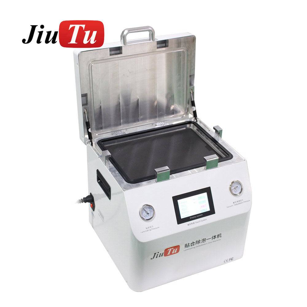
Images (from the two specified products, placed where they match the content)

At this point in a real process discussion, the key question is not “big or small machine.” It’s “what has to be controlled.” For larger panels, bed area, heating uniformity, and pressure distribution typically dominate.
Vacuum Laminating Machine Price: ranges, cost structure, and what to prepare before requesting a quotation
Pricing is a common place where projects drift. Not because people don’t understand cost—because information is missing at inquiry time.
Instead of quoting a single number, a better approach is price range + cost composition + hidden costs.
Price ranges (practical tier framing)
A vacuum laminating machine for LCD/OLED work typically falls into tiers:
-
Compact bench-scale units (phones / small tablets):
Usually lower capital cost, optimized for quick loading, simple operation, and frequent model changes. -
Mid-size production systems (tablets / HMIs / mixed sizes):
Higher cost because fixtures and bed size grow, and stable recipe control becomes more important. -
Large-bed heated platforms (large LCD, larger G+G, hot-melt capable lines):
Highest cost tier due to mechanical stiffness requirements, heated platen design, chamber size, and installation realities.
A key truth that should be stated plainly: different panel sizes, adhesive types, and fixture scope can move the price significantly even within the same tier.
What actually drives cost (the cost composition)
A quotation typically shifts because of:
-
Bed size + flatness tolerance (machining, stiffness, and assembly grade)
-
Vacuum system sizing (pump class, manifold, sealing design, filtration)
-
Thermal system (dual-plate heating, uniformity design, insulation, control)
-
Control system (PLC, recipe storage, HMI interface sophistication)
-
Fixture / mold scope (standard vs custom; number of models supported)
-
Safety and interlocks (over-temp, over-pressure, mechanical safety)
-
After-sales delivery (training, acceptance protocol support, spare kit)
In real terms, a “cheaper” machine can become more expensive if it causes high rework. The line pays for instability every day.
Information to provide before asking for price (so the recommendation is not guesswork)
If a recommendation is expected—not just a number—this list prevents wrong selection:
-
Maximum panel size used weekly (not a rare one-off)
-
Panel type mix: LCD, OLED, flat, edge-curved
-
Adhesive type: OCA film thickness range, LOCA presence, hot-melt/SCA requirement
-
Throughput target: pieces/day, shift length, how many fixtures per cycle
-
Top defects seen today: edge line bubbles, micro-bubbles, Newton rings, haze, misalignment
-
Site readiness: power limits, compressed air availability, space and access path
-
Fixture plan: existing fixtures vs new fixtures, number of models required
A short operational sentence that helps: without the defect list, the spec discussion becomes theoretical. Defects tell the process where it hurts.
Hidden costs that get missed (and later become budget surprises)
A practical budget should include:
-
Fixtures and molds (often multiple sets; one per model family)
-
Consumables (release liners, cleaning materials, anti-static supplies)
-
Wear parts (gaskets, seals, pads, filters)
-
Shipping and installation (especially for heavy large-bed platforms)
-
Ramp-up scrap (first-week tuning losses are normal)
-
Training and maintenance (vacuum curve logging, seal inspection routines)
Even a well-built vacuum laminating machine needs maintenance discipline. It’s not a set-and-forget tool.
How to Choose: a Step-by-Step process that can be executed, sampled, and accepted (8 steps)
This section is written as an operational flow. Each step starts with a concrete “result to obtain,” then explains why it matters and how to verify it.
Step 1 — Result: a locked scope of real panels and volumes
Confirm: top 10 panel models by weekly volume; max size used routinely; flat vs edge-curved ratio.
Why it matters: stage size and fixture strategy should match routine work, not rare cases.
How to verify: pull 4 weeks of rework logs or production orders and count actual models.
Step 2 — Result: a defined adhesive window and thermal requirement
Confirm: adhesive types used (OCA/LOCA/hot-melt), thickness range, whether heat is required.
Why it matters: heat and timing control requirements differ dramatically by adhesive.
How to verify: pick one high-volume panel; run a small DOE: vacuum time ±10 seconds, two press curves, two hold times, and temperature on/off if relevant. Log defects under the same inspection method.
Step 3 — Result: a defect map that points to control needs
Confirm: dominant defect patterns and where they appear (edge, corner, center).
Why it matters: edge bubbles often point to contact timing and press curve; scattered micro-bubbles point to vacuum + contamination.
How to verify: keep a consistent backlight station and photo method. Same brightness, same angle, same distance.
Real line detail: edge-line bubbles are the most common “looks fine until backlight” defect. The panel hides it in ambient light, then the backlight exposes it instantly.
Step 4 — Result: vacuum performance requirements expressed as acceptance metrics
Confirm: target vacuum level format (absolute or gauge), target build time with real load, allowable drift during hold.
Why it matters: vacuum numbers without time and hold behavior are incomplete.
How to verify: run a vacuum curve test with the real fixture and a typical dummy stack: time-to-target + 60–120 second hold drift, repeated after 20 cycles.
Step 5 — Result: verified pressure uniformity and platen parallelism on the actual bed
Confirm: required pressure range; uniformity across bed; parallelism under load.
Why it matters: non-uniform pressure creates haze and optical thickness issues that look like “bubble problems.”
How to verify: pressure mapping paper/sensors under a dummy plate; witness lamination at center + corners; compare haze/bubble density.
Step 6 — Result: an alignment system that is repeatable across shifts
Confirm: fixture datums, clamping repeatability, loading sequence, and whether it supports dry-fit checks.
Why it matters: misalignment rework is expensive and often blamed on the wrong root cause.
How to verify: ten-run repeatability test using two operators; measure edge offsets at fixed reference points.
Another real detail: shift handover is where repeatability gets tested. If alignment depends on “feel,” the first hour tends to expose it.
Step 7 — Result: a debubble strategy chosen by batch size and defect behavior
Confirm: whether debubbling is integrated or performed as a separate step; batch size needs.
Why it matters: some defects clear only after post-lamination pressure/temperature cycles.
How to verify: compare results after 1-hour rest + mild heat recheck. Panels that look clean immediately can still bloom micro-bubbles later.
A natural internal path for process context is the on-site guide: LCD lamination process guide.
Step 8 — Result: a written acceptance checklist agreed before purchase
Confirm: sample count, recipes, inspection method, pass/fail thresholds, and stability targets.
Why it matters: acceptance becomes a test plan, not a debate.
How to verify: document it as a one-page protocol and run it exactly.
Solution Matching: selecting setups by scenario (natural guidance, clear deliverables)
This section answers the unspoken question: what configurations fit what job types, and what delivery support typically comes with a serious setup.
Scenario A — Phone refurbishment and frequent model switching (compact, fixture-driven)
A compact vacuum laminator machine makes sense when the work is dominated by small screens, frequent model changes, and fast cycling. The goal is controlled vacuum + stable pressing + quick fixture swaps without making the bench workflow heavy.
Typical pairing in this scenario:
-
vacuum lamination + integrated bubble control (when the workflow is single-piece or small batch)
-
one clean handling station + one backlight inspection station
-
a fixture set that covers the highest-volume models
Scenario B — Mixed tablets / industrial HMIs (recipe stability and uniformity)
When panels are larger and model diversity is still high, recipe stability becomes the core requirement. This is where staged press curves, repeatable vacuum timing, and consistent alignment datums pay off.
Teams often underestimate fixture scope here. The machine may be capable, but yield depends on fixtures that hold flatness and reference points consistently.
Scenario C — Large flat panels and hot-melt capable workflows (heated bed, rigidity, distribution control)
For larger displays, stiffness and uniformity dominate:
-
bed size margin (not just “fits”)
-
temperature uniformity verification
-
pressure uniformity and platen parallelism
-
vacuum curve stability with real loads

Scenario D — Lamination + separate debubbling (when yield needs a second-stage safety net)
If micro-bubbles appear after rest or after mild heating, a separate debubbling step often stabilizes yield. This is especially true for larger panels or higher-value modules.
A clean internal navigation point for the debubbling step is: bubble remover machine series.
What can be delivered as part of a real setup (not just the machine)
A serious workflow usually includes more than hardware:
-
Sample validation support: panels/adhesive/fixture drawings used to confirm process windows
-
Fixture customization: datum definition, clamping strategy, flatness management
-
Parameter suggestion tables: baseline recipes by OCA/LOCA/hot-melt families
-
Installation and training: acceptance protocol execution + operator handover routine
-
Spare parts package: seals, pads, and maintenance items to avoid downtime
“Consultation-ready” information checklist (for fast model matching)
If a model recommendation is needed quickly, preparing these items makes the response precise:
-
maximum screen size used weekly
-
adhesive type (OCA/LOCA/hot-melt) and thickness range
-
daily output target
-
whether post-lamination debubbling is required
-
available power and compressed air conditions
-
main defect types seen today (edge line bubbles, micro-bubbles, haze, misalignment)
That list looks simple, but it eliminates most back-and-forth.
Defect Troubleshooting: symptoms + causes + priority order + minimal-change strategy
This is where field experience matters. The fastest way to lose time is to change three parameters at once.
Priority order (recommended on real lines)
-
contamination control and handling discipline
-
vacuum build time and hold stability (leaks)
-
press curve (pre-press/main/hold timing)
-
fixture flatness + platen parallelism
-
temperature uniformity (if heating is used)
-
alignment system repeatability
Minimal-change strategy (small steps, measurable outcomes)
A stable tuning method looks like this:
-
first adjust vacuum time +5 to +10 seconds
-
then adjust pre-press duration or level
-
then adjust main press ramp timing
-
then confirm sealing and fixture flatness
-
only after that change temperature or adhesive materials
Real scene sentence (because it happens): after a “quick tweak” of multiple settings, a line can’t tell which change fixed the problem—then the next shift breaks it again.
Troubleshooting table (expanded)
| Symptom on inspection | Likely root causes | Priority check order | Minimal-change action |
|---|---|---|---|
| Thin edge-line bubbles visible under backlight | edge seals too early; aggressive press ramp; uneven edge pressure | 2 → 3 → 4 | add vacuum +5–10s; soften pre-press; slow ramp into main press |
| Scattered pin-bubbles across active area | vacuum time short; leak drift; contamination | 1 → 2 | tighten cleaning routine; confirm vacuum curve; extend vacuum slightly |
| Corner haze / corner micro-bubbles on large panels | temperature non-uniform; pressure distribution | 4 → 5 | verify platen parallelism; run corner temperature soak; check pressure mapping |
| Newton rings / rainbow pattern zones | thickness non-uniform; over-compression; pressure uneven | 4 → 3 | verify pressure uniformity; increase hold time; reduce peak pressure if needed |
| Bubbles appear after 1-hour rest | incomplete consolidation; residual gas; insufficient hold stability | 3 → 2 | increase hold time; confirm vacuum hold drift; keep thermal conditions consistent |
| Misalignment shifts across runs | fixture datum weak; loading sequence drift; clamp repeatability | 6 | add hard datum stops; standardize loading sequence; verify clamp consistency |
Acceptance Checklist (table version) — the “publishable” part many teams forget
This checklist is designed for receiving a vacuum laminating machine and verifying it in a way that matches LCD/OLED lamination reality.
| Category | What to test | How to test | Pass logic |
|---|---|---|---|
| Vacuum curve | time to target vacuum with real load | fixture + dummy stack; record time-to-target | stable within defined window across repeats |
| Vacuum hold | leak drift during hold | hold 60–120s and log drift | drift stays below agreed threshold |
| Pressure uniformity | distribution across bed | pressure mapping / witness lamination | corners and center behave similarly |
| Platen parallelism | parallel under load | thickness checks / mapping | no consistent corner bias |
| Press curve | staged behavior | run pre-press/main/hold recipe | defect reduction without throughput collapse |
| Temperature uniformity (if heated) | corner vs center delta | multi-point probes after soak | delta within agreed window |
| Alignment repeatability | shift repeatability | 10-run test across operators | offset spread within acceptance band |
| Stability | continuous run stability | 20-cycle continuous test | defect rate doesn’t climb over cycles |
A small but important field note: acceptance should include a 1-hour rest + mild heat recheck for at least a few samples. Immediate inspection alone can be misleading.
Maintenance Rhythm (weekly / monthly / quarterly) — practical, not theoretical
A vacuum laminating machine stays stable when maintenance is boring and scheduled.
Weekly
-
wipe sealing surfaces and inspect gasket for residue or compression marks
-
log vacuum build time once per shift and review drift
-
quick fixture flatness check (straightedge + corner check)
Monthly
-
inspect vacuum lines and fittings for looseness
-
check clamp repeatability and fixture datums for wear
-
verify pressure mapping consistency (quick check, not a full study)
Quarterly
-
replace or rotate wear pads and seals as needed
-
validate temperature uniformity again if heated processes are used
-
run a short acceptance-style stability test (10 cycles) and compare to baseline photos
This rhythm prevents the most common slow failure: “everything works, then gradually it doesn’t.”
FAQ: Vacuum Laminating Machine (LCD/OLED Optical Bonding)
1) vacuum laminating machine — what is it used for in LCD/OLED rework?
It evacuates air and presses optical stacks under controlled timing so OCA/adhesive interfaces bond with fewer bubbles and more uniform thickness. It’s used for cover glass bonding, module refurbishment, and optical bonding workflows.
2) vacuum laminating machine principle: why do staged press curves reduce edge bubbles?
A staged curve keeps an escape path open longer. A gentle pre-press starts contact without sealing edges instantly, then main press completes wet-out. This reduces edge-line entrapment that shows under backlight.
3) vacuum laminating machine specs: what should be tested, not trusted on paper?
Vacuum build time with real load, vacuum hold drift, pressure uniformity, platen parallelism under load, and temperature uniformity (if heated). These can’t be validated by a single brochure number.
4) What’s the practical difference between a vacuum laminator and a vacuum OCA laminating machine?
“Vacuum laminator” is often used broadly. A vacuum OCA laminating machine implies the workflow is tuned for OCA film lamination, including stable evacuation and controlled pressing suitable for optical stacks.
5) How does chamber volume affect bubbles?
A larger effective volume (chamber + plumbing + fixture cavities) requires more pumping throughput to reach target vacuum quickly. If build time is slow, operators shorten evacuation, and micro-bubbles increase.
6) What causes micro-bubbles that appear “randomly” across the active area?
Usually contamination or insufficient evacuation time, sometimes leak drift. The fix order is typically cleaning discipline → vacuum curve check → small vacuum time increase.
7) When does LOCA change the machine selection logic?
LOCA introduces flow and curing variables. Vacuum turbulence, contact timing, and press ramp become more sensitive. Selection should emphasize stable vacuum behavior and controllable pressing over raw peak pressure.
8) Is heating always needed for LCD/OLED lamination?
No. Many OCA workflows can run without heat. Heating becomes important for hot-melt processes and when viscosity control is needed to stabilize wet-out and thickness uniformity.
9) How to verify temperature uniformity without complicated instruments?
A multi-point probe after a soak time plus a witness lamination mapped across bed positions works well. Consistent corner failures often signal distribution issues.
10) When is a separate debubble step worth adding?
When micro-bubbles persist after lamination or appear after rest/heat. A separate step can stabilize yield for large or high-value panels. Navigation point: bubble remover machine series.
11) What’s the most reliable way to prevent “bubble return” after inspection?
Increase consolidation hold stability, verify vacuum hold drift, and add a recheck after 1-hour rest plus mild warming. If bubbles bloom later, the hold window was too short or unstable.
12) What internal reference helps organize an LCD lamination workflow?
The process-oriented guide is useful for structuring SOP steps and defect logic: LCD lamination process guide.
Closing notes + 3 actionable next steps
A vacuum laminating machine is only “good” when it produces predictable vacuum curves, uniform pressing, and repeatable alignment across shifts. The selection process should look like a test plan, because the defects are measurable and the fixes are usually small—but only if the machine is stable.
Three next steps that can be executed immediately:
-
Write a one-page acceptance protocol (vacuum curve + hold drift, pressure mapping, temperature uniformity, alignment repeatability, 20-cycle stability).
-
Run a controlled sampling test on one high-volume model (vacuum ±10s, pre-press timing change, hold time change) and log defect photos consistently.
-
Lock the fixture and maintenance plan (datums, flatness checks, gasket cleaning rhythm) before scaling output.