
Bubble-free optical bonding is a result that can be checked, repeated, and improved. It is not something that appears simply because a vacuum button exists on a machine. This LCD laminating machine guide is written for workshops, operators, and procurement teams that want stable clarity, predictable yield, and fewer rework loops across LCD and OLED stacks. It explains how bubbles actually form, which controls remove them, and how to choose equipment as a complete line instead of a single purchase.
In day-to-day production, the “best” process is often the one that stays stable when the room is busy, staff rotate, and material batches vary. A practical selection approach starts from failure patterns and works backward to equipment capability. That mindset also makes an OCA bonding machine purchase easier to defend internally, because the decision is tied to measurable defects, acceptance checks, and cost of rework.
What OCA optical bonding changes in the finished display
OCA (Optically Clear Adhesive) is a transparent adhesive layer used to bond cover glass to a display module or to a touch-and-display stack. When bonding is clean, internal reflections drop and the stack looks more “solid” under strong light. Many assemblies also feel more integrated because the air gap is removed and parallax is reduced.
The same optics that make bonding valuable also make defects obvious. A tiny bubble can scatter light and show as sparkle under angled inspection. A single dust particle can become a long-term bubble seed after thermal exposure or vibration. That is why selection cannot stop at “vacuum exists” or “pressure is high.”
Bubble mechanisms that matter in real workshops
Many teams assume “stronger vacuum means fewer bubbles.” On the bench, the most stubborn bubbles rarely come from low vacuum alone. They come from air being trapped because an escape path closes too early, or because adhesive stress pulls microvoids back after pressing.
Common mechanisms behind bubble formation include early edge sealing, adhesive rebound, blocked vent routes, and contamination-driven nucleation. A panel can look perfect immediately after pressing and still develop microbubbles later if stress and temperature behavior are not controlled. When these patterns show up, the fix is usually found in ramp shape, dwell logic, flatness support, and cleanliness discipline—not in chasing a single headline spec.
The workflow as an SOP: target → control points → failure signs → adjustments
This section is written like a practical SOP. Each stage has one goal, a short list of controls, clear failure symptoms, and corrective actions. That structure makes it easier to train operators and to evaluate equipment during trials.
Stage 0: Conditioning (materials and environment)
Target: stable film behavior and predictable tack.
Control points: consistent room conditions, anti-static handling, controlled storage, and a defined acclimation period before lamination.
Failure signs: “random dot bubbles,” sudden haze patches, and unstable day-to-day yield.
Adjustments: tighten dust control, reduce static sources, and standardize acclimation timing so films are not applied while stressed or cold.
Stage 1: Surface preparation and verification
Target: remove residues and particles that later become bubble seeds.
Control points: consistent cleaning steps, edge attention, residue removal, and repeatable inspection lighting.
Failure signs: halos around dust points, repeated defects in similar locations, and streak-like contamination lines.
Adjustments: add tack-rolling steps, refine wipe direction rules, and enforce a minimum edge inspection standard before stacking.
Stage 2: Film placement (OCA and polarizer layers)
Target: flat laydown with no wrinkles and no trapped liner fragments.
Control points: stable referencing, controlled tension, consistent laydown speed, and a short relaxation pause when film stress is high.
Failure signs: crease-shaped bubble lines, edge whitening, local haze, and early edge lift.
Adjustments: improve placement tooling, slow the laydown where creases appear, and standardize the “rest time” used to relieve film tension.
Stage 3: Alignment and stack locking
Target: prevent shear and drift during evacuation and compression.
Control points: fixture referencing, platen parallelism, stable clamping behavior, and a consistent loading sequence.
Failure signs: corner crescent bubbles, diagonal stress lines, shift marks after pressing, and uneven perimeter width.
Adjustments: reinforce flatness support, add mechanical stops, and reduce free movement before evacuation begins.
Stage 4: Vacuum evacuation and press cycle
Target: remove air first, then compress without sealing the perimeter too early.
Control points: evacuation timing, vacuum stability, a multi-step pressure ramp, and a defined dwell at key stages.
Failure signs: edge bubbles that survive the cycle, corner clusters that repeat by position, and trapped pockets that refuse to collapse.
Adjustments: slow the early ramp, extend evacuation, check seals and leak behavior, and avoid aggressive early clamping that closes escape routes.
Stage 5: Post-lamination debubbling (pressure and mild heat)
Target: collapse microbubbles that remain after vacuum pressing.
Control points: stable pressure profile, moderate and uniform temperature, consistent load method, and repeatable cycle time.
Failure signs: sparkle microbubbles under angled light and tiny edge voids that grow after heating.
Adjustments: tune debubbling cycles to stack type, avoid aggressive heating, and validate that load placement does not create pressure gradients.
Stage 6: Inspection and acceptance logging
Target: confirm clarity now and stability after controlled exposure.
Control points: angled-light inspection, dark-screen checks, edge scanning, and periodic stability sampling.
Failure signs: delayed bubble growth, ring artifacts, local haze, and edge lift after mild heating.
Adjustments: tighten acceptance criteria, log defect maps consistently, and lock recipes only after stability is demonstrated.
This SOP framing also helps procurement. When machines are compared by “which stage risk is reduced,” selection feels grounded rather than brand-driven.
Machine categories that build a bubble-free optical bonding line
A bubble-free outcome usually comes from a line, not a single machine. Each category removes a different failure mode.
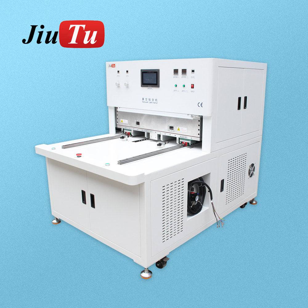
Vacuum laminators for primary bonding
Vacuum lamination removes most air before compression and improves repeatability across operators. The real differentiators are rigidity, flatness support, ramp control, and recipe repeatability. Those features often decide whether corners remain clean when panel size increases.
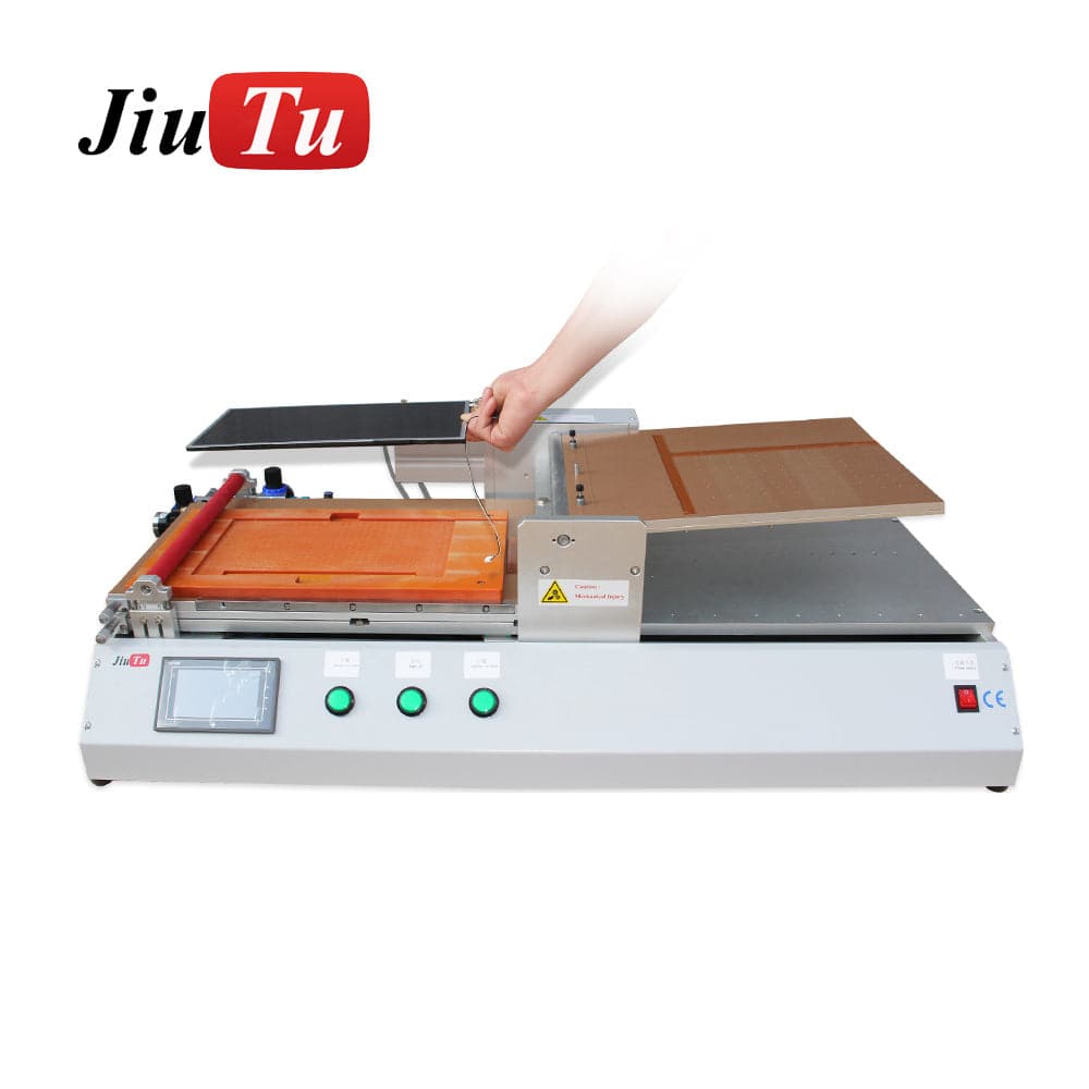
Film placement tools for OCA and polarizer layers
Film placement is where wrinkles become air channels later. It is also where dust transfer happens most frequently if handling is not disciplined. A stable placement step reduces edge stress and improves downstream yield more than most teams expect.
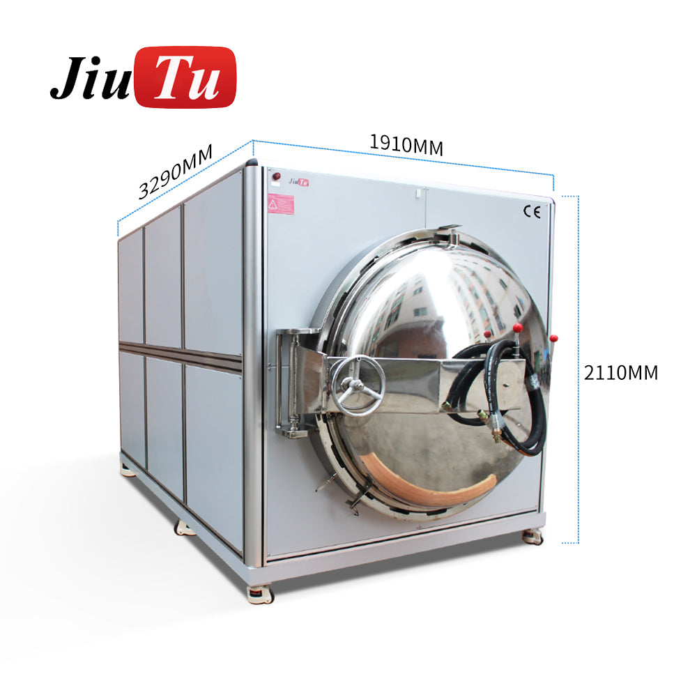
Bubble remover systems for microbubble collapse
Post-lamination debubbling is a stabilizer stage. It reduces sparkle microbubbles and improves cosmetic grade when stacks are sensitive. It is most valuable when larger active areas make microvoids more visible.
Fixtures and molds for flatness and force distribution
Fixtures are the “hidden machine.” They define flatness support, vent routes, and placement repeatability. When corner bubbles always appear in the same location, fixtures deserve first attention.
To quickly compare equipment by function and application, it helps to browse the optical bonding category and filter by process stage and size: OCA bonding machine.
OCA thickness and stack matching (practical guidance without overselling)
OCA thickness selection is usually a trade-off between optical crispness, gap tolerance, and process sensitivity.
Thinner films often deliver sharper optical feel but punish dust and flatness variation. Mid-range films tend to balance handling and appearance across many stacks. Thicker films can tolerate minor surface variation, yet they demand careful ramp and dwell control to avoid trapping air.
The key point is not to chase a single “best” thickness. The better approach is to list the dominant stack families in the workshop—phone-size modules, automotive displays, industrial HMI panels, large panels—and then validate a stable window during trial.
Defect-to-parameter mapping that sounds like the shop floor
Process improvements become faster when defects are translated into likely controls. The patterns below reflect what typically shows up during lamination trials.
Corner crescents and corner clusters
This pattern often points to uneven support or early edge sealing. A common mistake is to change adhesive first, even when the bubble shape and location stay consistent.
What tends to help is improved flatness support, better ramp shaping, and a longer evacuation phase that keeps escape paths open. If the defect repeats in the same corner, fixture verification is usually faster than recipe guessing.
Edge bubbles that survive pressing
Edge bubbles can persist even when vacuum appears strong. This often happens when early clamping closes the edge path before air evacuates fully.
The fix usually looks unglamorous: slower early ramp, longer evacuation hold, and better perimeter support. It is also worth checking whether operators load stacks with slight skew, because skew can make one edge seal early.
Newton rings and rainbow artifacts
These artifacts often come from microscopic spacing gradients and uneven compression. Better flatness, uniform pressure distribution, and more consistent tooling support tend to reduce them.
A “more pressure” approach can backfire if it increases gradients. Uniformity and stability usually outperform force.
Delayed bubble growth after mild heating
When panels look clean initially and then develop microbubbles, adhesive stress and microvoids are common suspects. Post-lamination debubbling and controlled dwell often reduce this behavior. Temperature uniformity matters here because hotspots can trigger local stress release.
This is one reason an OCA bonding machine should be evaluated with a stability sampling step, not only immediate appearance checks.
Scenario-based selection table (use case → priorities → pairing logic)
Different scenarios punish different weaknesses. The table below ties common applications to the selection priorities that usually matter most.
| Scenario | Typical risk pattern | Primary priorities | Practical pairing logic |
|---|---|---|---|
| Phone-size modules | dust dots, edge sealing | cleanliness discipline, stable alignment | film placement + compact vacuum lamination + optional debubbling |
| Automotive displays | stability after thermal exposure | edge stability, uniformity, repeatable recipes | rigid fixtures + vacuum lamination + debubbling |
| Industrial HMI panels | mixed stack thickness | fixture adaptability, recipe control | vacuum lamination + strong tooling + post-debubble |
| Large panels | corner clusters, warp sensitivity | rigidity, size capacity, tooling path | large-area vacuum lamination + bubble remover + custom fixtures |
When comparing different size ranges quickly, the optical bonding category page is a practical shortcut for procurement teams that want to filter by application and workflow stage: OCA bonding machine.
Common screen size bands and recommended “process windows” (ranges, not recipes)
The ranges below are not meant to be copied as final recipes. They are meant to narrow the search space during trials. After a stable window is found, the acceptance template later in this guide is what locks the final recipe.
Small active areas (phone-size stacks)
Small stacks can look easy, yet OLED sparkle microbubbles can be stricter than expected. Cleanliness and film handling matter more than raw compression. A gentle early ramp and a controlled dwell often reduce edge sealing problems.
A typical sign of a handling issue is bubbles that follow a crease-like line. In that case, the placement step needs attention before press settings are changed.
Medium active areas (tablet and mid-size industrial stacks)
As size increases, corner behavior becomes more sensitive. Fixtures must support flatness without over-constraining the edges. Multi-step ramping and stable evacuation timing often produce more consistent results than fast cycles.
If defects concentrate in corners, flatness support and platen parallelism deserve early checks. Changing adhesive is rarely the fastest first move.
Larger active areas (upper industrial and signage segments)
Large panels magnify small support errors. Evacuation tends to require more patience, and recipe repeatability becomes critical. Post-lamination debubbling typically produces a visible improvement in cosmetic grade on these sizes.
For these panels, “range is not a recipe” matters most. A range can narrow the process, but only acceptance logging can prove stability.
Quick scoring table for procurement (copy-friendly)
This module is intentionally designed for internal sharing. It helps procurement and engineering compare models without turning the discussion into personal preference.
Each category is scored from 1 to 5. The total gives a quick comparison across machines and vendors.
A. Vacuum stability
1 = drift or inconsistent hold
3 = stable with occasional sensitivity
5 = stable hold and predictable evacuation behavior
B. Pressure ramp and dwell control
1 = mostly on/off control
3 = basic ramp with simple dwell
5 = multi-step ramp with repeatable recipes and lockable parameters
C. Temperature uniformity (if used)
1 = uneven and unstable
3 = workable with monitoring
5 = uniform behavior under load and stable control
D. Platform rigidity and parallelism
1 = visible flex or uneven corners
3 = solid but sensitive to tool changes
5 = stable under load and repeatable across cycles
E. Fixture ecosystem and customization path
1 = limited options
3 = workable but slow to adapt
5 = clear fixture path and validation approach
F. Inspection support and traceability
1 = basic settings only
3 = recipe storage without strong traceability
5 = recipe recall, alarms, and stable parameter management
G. Maintainability
1 = hard access and frequent drift
3 = normal maintenance
5 = easy seal checks and stable calibration routine
Interpretation:
-
High totals usually correlate with faster stabilization and lower rework.
-
Mid totals can still work if SOP discipline is strong and stack variety is limited.
-
Low totals often produce random defects that waste engineering time.
This scoring style fits a real LCD laminating machine guide because it rewards stability and repeatability, not only speed claims.
A short decision tree that prevents “wrong first purchase”
When teams feel stuck, a decision tree can stop endless debates.
Step 1: Size capacity and handling stability
If the dominant workload includes larger panels, rigidity and size capacity become first constraints. If the dominant workload is phone-size, handling efficiency and placement control become the first constraints.
Step 2: Dominant defect pattern
If sparkle microbubbles drive rework, debubbling capability becomes a priority. If corner crescents dominate, fixture flatness support and ramp control move to the top.
Step 3: Stack variability
If stacks change frequently, fixture adaptability and recipe management matter more than peak speed. If stacks are stable and repeated, deeper optimization on one recipe can deliver strong ROI.
Step 4: Stability requirement
If failures appear after mild heating, focus should shift to dwell, uniformity, and post-debubble strategy. If failures appear immediately, focus should stay on cleanliness, ramp shape, and escape paths.
Acceptance checklist and record template (usable during trial and procurement)
This module is meant to increase conversion and reduce risk. It gives workshops a way to evaluate machines and lock recipes without relying on memory or verbal “looks good.”
A. Incoming verification (before trial)
-
Rigidity and basic alignment checks under typical load conditions.
-
Seal integrity checks and stable vacuum behavior over a hold period.
-
Temperature behavior checks if heating is part of the process.
-
Safety functions verified (interlocks, alarms, relief behaviors).
B. Trial run logging (single stack first)
Record the stack definition clearly: cover glass thickness category, OCA type, panel size band, presence of touch layers. Keep the first trial narrow so defects map to fewer variables.
Log evacuation timing, ramp steps, dwell points, and any heating or debubbling steps. Also log handling steps like cleaning sequence, tack-rolling method, and any relaxation pauses used in film placement.
C. Output inspection (repeatable method)
-
Angled-light inspection for sparkle, haze, and fine streaks.
-
Dark-screen checks for rings and local contrast distortion.
-
Edge scan for voids and early lift.
-
Corner checks for crescents and clusters.
-
Photo log with a simple grid position reference.
D. Stability sampling (lightweight but meaningful)
Run a controlled stability sampling step on a small subset, then re-check edges, corners, and sparkle points. If delayed bubbles appear, the record should show whether the root cause is likely dwell, uniformity, or debubbling behavior.
Copy-ready record template
Project name:
Panel size band:
Stack structure:
OCA category:
Date / batch:
Vacuum stage
-
Evacuation timing:
-
Hold stability notes:
-
Seal and leak notes:
Press stage
-
Ramp steps:
-
Dwell points:
-
Peak pressure category:
Temperature stage (if used)
-
Heat level category:
-
Uniformity notes:
Debubble stage (if used)
-
Pressure profile category:
-
Heat level category:
-
Time category:
Inspection results
-
Active area bubbles:
-
Corner defects:
-
Edge defects:
-
Rings/haze:
-
Notes + photo IDs:
This template closes the loop: ranges narrow the search space, and acceptance logs lock the recipe. That prevents “range arguments” from turning into endless debates.
ROI and capacity logic that procurement teams can defend
ROI discussions fail when cycle time is treated as the only lever. A more realistic model uses three parts: cycle time, yield after full inspection, and rework share.
A faster press that produces frequent microbubble rework can lose in total output. A slightly slower cycle with stable yield often wins because operators spend less time repeating work. This is also why maintainability matters: a process that drifts due to seals or flatness changes will quietly burn hours.
When procurement decisions require justification, connecting cost to defect patterns is powerful. The acceptance template and the scoring table provide that connection in a format that can be shared internally.
Internal linking and browsing that feels natural
When a quick overview of different size segments and machine categories is needed, the optical bonding collection page is easier than hunting individual product links. It allows filtering by use case and helps align internal discussions around workflow stages rather than brand names. A practical starting point is the OCA bonding machine category page.
For teams building internal training material, a companion reference helps unify vocabulary and workflow order. The internal post titled LCD laminating machine guide is a useful addition when writing SOPs and inspection standards.
FAQ: bubble-free LCD/OLED lamination and selection decisions
Why do bubbles show up even when vacuum seems strong?
Vacuum can remove air, yet early edge sealing can trap air before it exits. Ramp control, evacuation timing, and fixture geometry often decide whether an escape path stays open.
Why do bubbles sometimes appear after a panel looked clean?
Microvoids and adhesive stress can reveal themselves after mild heating or time. Post-lamination debubbling and controlled dwell behavior often reduce delayed growth.
What usually fixes a “same corner” bubble problem?
Repeated corner location often points to flatness support, platen parallelism, or fixture geometry. Recipe changes can help, but mechanical support checks are often faster.
Why can “more pressure” make rings worse?
Rings often relate to spacing gradients and uneven compression. Higher force can increase gradients if support is uneven. Uniformity and tooling support usually beat raw force.
Is debubbling always required?
Not always, but it becomes more valuable as panel size increases or cosmetic standards tighten. It also helps when microbubbles remain after vacuum pressing despite stable settings.
How should “process windows” be used safely?
Ranges narrow the search space during trials. Final recipes should be locked only after acceptance logging and stability sampling confirm repeatability. That is the difference between a guide and a guaranteed formula.
Summary and next steps
Bubble-free optical bonding is built from stable air-path control, stress control, and disciplined cleanliness. Vacuum is important, yet ramp shape, dwell logic, uniformity, and fixture support decide whether corners and edges stay clean across batches. A well-chosen OCA bonding machine line reduces rework, improves clarity, and makes yield predictable instead of random.
This LCD laminating machine guide also emphasizes a practical workflow loop: use ranges to narrow settings, use acceptance logs to lock recipes, and use defect mapping to decide whether the next improvement belongs in tooling, handling, or the press cycle. For quick category filtering and size comparison, the optical bonding section remains the simplest navigation path: OCA bonding machine. In closing, this LCD laminating machine guide is designed to read like workshop experience—because stable optical bonding comes from repeatable actions, not from marketing terms.