
Optical bonding projects fail in quiet ways. A seal drifts a little. A platen warms unevenly. A fixture flexes at one corner. Then bubbles return after a rest period, haze shows under backlight, or Newton rings appear near the edge ink. Those issues are rarely “operator mistakes.” They are usually specification gaps that were never written down, never tested, and never accepted.
A purchase decision becomes safer when it reads like a process qualification plan. The right adhesive bonding machine is not the one with the most impressive brochure numbers. It is the one that holds vacuum, applies pressure evenly, keeps temperature stable, and aligns predictably with the real stack-up. The goal is simple: lock a measurable process window that can be repeated across shifts and documented in acceptance terms.
This guide focuses on benefits, use cases, matching strategies, common issues, and selection logic. It also includes contract-ready verification methods for vacuum, pressure, temperature, and CCD alignment. Product examples are placed as workflow modules, so the equipment choice stays tied to defect risk and process needs.
What “adhesive bonding” means in optical stacks
Optical bonding joins layers into one clear stack while minimizing air, stress, and optical distortion. Typical assemblies include cover glass + OCA film + LCD, cover glass + touch sensor + LCD, and glass-to-glass industrial modules. Cosmetics matter because inspection is harsh: angled light, polarized glare, backlight uniformity, and corner scrutiny.
Adhesive selection defines the controls needed on the bonding line. OCA film (optically clear adhesive film) provides consistent thickness and clean handling, so it often supports stable appearance on flat builds. LOCA (liquid optical clear adhesive) can fill gaps, yet it brings dispensing stability and curing discipline. Hot-melt processes (often referenced as SCA/OCF-style workflows) demand more from temperature stability and pressure ramp control.
Even with the same adhesive, geometry changes everything. Printed borders can “pinch” early and trap air channels. Narrow bezels make small offsets look large. Raised inks create local pressure peaks that can form rings. Because of that, a machine decision should be made with the fixture and stack geometry in mind, not only the panel diagonal.
Build the workflow map before choosing equipment
Optical bonding yield is a system outcome. A press cannot fix dust that was introduced during staging. A vacuum chamber cannot compensate for inconsistent film conditioning. A CCD station cannot rescue a warped carrier plate. The workflow map keeps responsibility clear and keeps selection realistic.
The four modules that decide yield
1) Surface preparation and handling
Cleaning method, ESD and ionization, dust strategy, covered staging, and storage discipline.
2) Alignment + lamination/bonding
Vacuum evacuation, pressure profile, temperature control, and fixture support.
3) De-bubbling / stabilization
A pressure and/or heat cycle that collapses residual micro-bubbles and stabilizes the bond after lamination.
4) Inspection discipline
Angled light scan, backlight check, edge and corner checks, plus a timed re-check after rest.
Each module has a “defect signature.” Dust tends to show as bubble trails or localized haze. Weak vacuum stability often shows as bubble return. Uneven pressure frequently shows as thickness gradients, Newton rings, or corner haze. Alignment problems show near bezels and printed borders, where the eye notices offsets first.
A practical buying plan ties equipment to these signatures. That is how specifications become meaningful, rather than decorative.
Define the bonding job so it can be quoted and accepted
Document the stack-up like a recipe
A one-page “layer recipe” prevents misunderstandings. It should list substrate type, thickness, coating notes, printed borders, raised features, and edge structures. A short note on cosmetic targets also helps: allowable bubble size, bubble count per area, edge tunnel tolerance, ring sensitivity, and haze thresholds under defined inspection lighting.
Fixturing belongs in the same document. Connector clearances, bezel steps, and ink borders often force tooling decisions. Those tooling decisions then change pressure distribution and air evacuation behavior. When the fixture arrives late, the machine often gets blamed for what the fixture caused.
Specify usable area, not catalog maximum
Catalog “maximum size” can be misleading. The real requirement is usable working area after fixture margins, edge protection, and gasket placement. Long screens and unusual shapes should be checked by drawing, not by diagonal size.
Multi-up layouts can improve throughput on larger beds. That approach works only when platen rigidity and pressure uniformity remain stable across the loaded area. Without uniformity, multi-up becomes a defect multiplier.
Define throughput as “good parts per hour”
Cycle time is only one piece. Cleaning, alignment verification, film handling, and inspection steps often dominate takt time. High-mix environments also need quick changeovers, stored recipes, and fixtures that can be swapped without re-learning the process.
A slower cycle with fewer reworks can outperform a faster cycle that produces unstable bonds. That trade-off is common in optical work, where rework risk is high.
Buying dimensions that prevent expensive surprises
Vacuum: stability and leak-rate matter most
Vacuum control is not only about reaching a low pressure. The most important features are repeatable pumpdown, stable isolation, and predictable release behavior. These factors directly influence trapped air paths and bubble return after rest.
Common reference ranges for optical lamination (guidance, not promises):
-
Many OCA film lamination processes are written around ≤ 5–10 kPa absolute in the chamber.
-
Larger areas or stricter cosmetics may require tighter targets, but stack geometry still sets the practical limit.
Leak-rate test that fits acceptance terms:
-
Pump down to the specified setpoint.
-
Isolate the chamber by closing the valve.
-
Record the pressure rise for 5–10 minutes.
-
Write acceptance as ≤ X kPa rise over Y minutes under defined conditions.
This test is attractive because it is objective, repeatable, and fast. It also correlates well with bubble return problems, especially when seals are marginal.
Pumpdown repeatability matters too. A stable system should reach setpoint within a predictable time band across repeated cycles. When pumpdown time varies widely, moisture, leaks, or valve behavior may be unstable.
Pressure: uniformity and profile beat peak force
Optical bonding needs enough pressure to wet-out adhesive and close micro-gaps. Too much pressure can stress thin glass, distort modules, or lock thickness gradients into the bond. Those gradients often show later as Newton rings or localized haze.
Two questions matter more than “maximum tonnage”:
-
How evenly is pressure applied across the working area under real tooling?
-
How controllable is the pressure ramp, hold, and release profile?
How to measure pressure uniformity during evaluation:
-
Pressure-sensitive film mapping: place film across a grid, run the cycle, compare density across zones.
-
Thickness mapping: use a compressible standard layer and measure thickness across points after the cycle.
-
Fixture rocking check: verify support points prevent tilt and early edge pinching.
Acceptance clause template:
“Under the agreed test fixture and load, pressure distribution across the defined working area shall remain within ±___% of the mean, verified by pressure-sensitive film or an agreed equivalent method.”
This clause links the spec to a method. That link is what makes acceptance enforceable.
Temperature: uniformity is the real control
Temperature affects adhesive flow, wetting behavior, and long-run repeatability. Hot-melt bonding depends heavily on it. Even temperature-assisted OCA processes can become more stable with uniform heat, especially on larger plates.
A high maximum temperature does not guarantee usable control. Optical bonding usually benefits more from stable setpoint behavior than from extreme setpoints.
Common acceptance targets used in industry documents:
-
±2°C to ±5°C uniformity across the platen at a defined setpoint, measured after stabilization.
-
Overshoot and drift limits written as measurable tolerances over time.
How to test temperature uniformity:
-
Place multiple probes (or a calibrated mapping tool) across the platen in a defined grid.
-
Stabilize for a fixed time at setpoint.
-
Record point-to-point variation and drift over time.
The test should be done at a realistic operating temperature, not at room temperature. Plate behavior can change after warm-up.
Alignment: CCD performance should be written as repeatability
Alignment issues are usually cosmetic-first. Narrow bezels, printed borders, and edge ink make offsets obvious. Functional alignment also matters on touch stacks and layered assemblies.
For alignment, “looks aligned” is not a metric. The evaluation becomes stronger when it uses measurable clauses.
Two acceptance metrics:
-
Accuracy: mean offset from target (X/Y and rotation if needed).
-
Repeatability: variation across cycles (often written as 3σ).
Practical verification method:
-
Use a fiducial-marked test panel.
-
Run 20–30 consecutive cycles with the same recipe and fixture.
-
Measure offsets with an agreed method (camera measurement, microscope reference, or optical comparator).
-
Report mean error and repeatability.
When a CCD station is selected, the clause should specify the fiducial pattern, measurement method, and the number of cycles. That prevents “one perfect demo cycle” from substituting for stability.
Defects and what causes them on the shop floor
Bubbles during lamination and bubble return after rest
Large bubbles during lamination often come from trapped air paths, early edge sealing, or vacuum timing that seals before evacuation completes. Bubble return after rest often correlates with leak stability, release timing, and edge channel behavior.
Leak-rate isolation testing is one of the best predictors. A system that cannot hold vacuum steadily is more likely to allow micro-bubbles to grow after the cycle ends.
Edge tunnels
Edge tunnels often form when edges seal early and trap a channel that cannot evacuate. Fixture design, staged vacuum timing, and controlled first contact often reduce this issue. More pressure is not always helpful; higher pressure can worsen early pinching.
Newton rings and thickness gradients
Newton rings typically signal thickness variation across the optical interface. Platen flatness, pressure uniformity, and fixture support dominate this outcome. A uniformity mapping test and a flatness check are more protective than any single brochure line.
Haze and shimmer
Haze can come from residue, moisture, micro-scratches, or uneven wet-out. Temperature stability can help, but surface preparation discipline often decides the final result. Adhesive storage and conditioning also matter, especially for films sensitive to humidity.
Misalignment near bezels
Misalignment becomes obvious when the bezel is narrow or the printed border is strict. Mechanical referencing can work, but CCD alignment reduces variation in high-mix environments or in builds where edge cosmetics are tight.
Spec checklist and acceptance criteria that can be signed
This section is designed to be copied into procurement and adjusted for the real stack. Values are placeholders by design. The important part is the structure: a measurable item and a defined method.
Vacuum spec checklist
Request in quotation:
-
Vacuum setpoint capability in kPa absolute
-
Pumpdown time to setpoint under defined conditions
-
Leak-rate (pressure rise) during isolation
-
Recipe controls: staged vacuum, hold time, controlled release
Acceptance test template:
-
“System shall reach ≤ ___ kPa abs within ___ seconds (empty chamber or with agreed fixture, specified).”
-
“After isolation at setpoint, pressure rise shall be ≤ ___ kPa over ___ minutes.”
Notes that prevent disputes:
-
Define gauge calibration method and reference.
-
Specify whether the test uses an empty chamber or a standard fixture load.
-
Fix test duration and sampling interval.
Pressure spec checklist
Request in quotation:
-
Working pressure range under load
-
Ramp profile control (ramp time, hold time, release behavior)
-
Pressure uniformity across defined area
-
Platen flatness specification or mapping method
Acceptance test template:
-
“Under agreed fixture and load, pressure distribution across the defined area shall be within ±___% of mean, verified by pressure film or equivalent.”
-
“Pressure ramp time to target shall be ≥ ___ seconds.”
-
“Platen flatness across the defined area shall be ≤ ___ mm (method defined).”
Simple verification methods:
-
Pressure film grid mapping.
-
Thickness mapping using a compressible standard.
-
Dial indicator or mapping tool for platen flatness.
Temperature spec checklist
Request in quotation:
-
Setpoint range needed for the process
-
Uniformity at setpoint after stabilization
-
Overshoot limit and drift limit
-
Warm-up time to stable performance
Acceptance test template:
-
“At °C setpoint, measured at ≥ ___ points after ___ minutes stabilization, deviation shall be within ±°C.”
-
“Overshoot shall not exceed ___°C above setpoint.”
-
“Drift over ___ minutes shall be ≤ ___°C.”
CCD alignment spec checklist
Request in quotation:
-
Accuracy and repeatability targets
-
Calibration method and frequency
-
Fiducial recognition capability and lighting control
-
Fixture interface and reference strategy
Acceptance test template:
-
“Using agreed fiducial test panel, mean alignment error shall be ≤ ___ mm.”
-
“Repeatability across ___ cycles shall be ≤ ___ mm (3σ).”
-
“Rotation error shall be ≤ ___ degrees (if applicable).”
A comparison table that keeps evaluation practical
| Decision item | What to ask for | How to verify during trial | What to write into acceptance |
|---|---|---|---|
| Vacuum setpoint | kPa abs target | Pumpdown to setpoint | “Reach ≤ ___ kPa abs within ___ s” |
| Vacuum stability | Leak-rate clause | Isolation test 5–10 min | “Rise ≤ ___ kPa / ___ min” |
| Pressure control | Ramp/hold/release | Repeat runs on same stack | “Ramp ≥ ___ s, hold ___ s” |
| Pressure uniformity | ±% across platen | Pressure film grid | “Uniformity ±___%” |
| Platen flatness | Deviation across area | Mapping method defined | “Flatness ≤ ___ mm” |
| Temperature uniformity | ±°C at setpoint | Multi-point mapping | “Uniformity ±___°C at ___°C” |
| Alignment performance | Accuracy + repeatability | Fiducial test 20–30 cycles | “Mean ≤ ___ mm, 3σ ≤ ___ mm” |
| Recipe management | Stored recipes/logs | Changeover + return test | “Recipe recall + parameter lock” |
| Serviceability | Wear parts access | Inspection + service steps | “Service interval + spares list” |
A short table like this tends to reduce evaluation emails and prevents subjective “feels better” conclusions. It also improves internal alignment when multiple sites evaluate equipment.
Trial plan that catches drift, not only a clean demo
Optical bonding equipment can look perfect for one cycle. Drift tends to appear after warm-up, after repeated cycles, or after fixture swaps. A trial plan should expose those conditions.
Recommended trial structure
Warm-up and stabilization
-
Warm the system until vacuum, temperature, and motion behavior stabilize.
-
Record stabilization time and confirm setpoint behavior.
Phase 1: early cycles
-
Run 5 cycles.
-
Inspect immediately under angled light and backlight.
-
Record any bubbles, haze, rings, and edge behavior.
Phase 2: steady-state
-
Run 15–20 continuous cycles.
-
Inspect again with the same lighting and the same criteria.
-
Record drift in defect patterns and alignment.
Rest-period re-check
-
Hold a sample set for a defined rest period.
-
Re-check for bubble return, edge tunnels, and ring emergence.
Inspection standard that reduces arguments
-
Angled light scan along edges and corners.
-
Backlight inspection for haze, rings, and micro-bubbles.
-
A photo guide or written defect standard with pass/fail thresholds.
-
A defined viewing distance and inspection angle for consistency.
This structure makes the trial less emotional and more objective. It also supports acceptance terms because the test method is already practiced.
Environment and upstream controls that protect appearance
Stable results depend on more than the bonding station. In optical work, upstream variability becomes a defect generator.
Cleanliness and dust control
Dust can seed bubble trails and local haze. Covered staging, clean benches, and disciplined wipe methods reduce that risk. Ionization can help when static attraction is strong. ESD controls also protect sensitive stacks, especially when thin films are handled.
When a cleanroom is available, the cleanliness class should be written into the process plan. If a full cleanroom is not used, local clean zones and disciplined staging can still improve consistency.
Surface preparation: cleaning, plasma, primer
Surface energy influences wet-out. Plasma treatment can help in certain builds, especially when surfaces are hard to wet uniformly. Primers can be useful for specific substrates, but compatibility matters and must be verified with the adhesive.
A practical approach is to document surface preparation steps the same way machine parameters are documented. That keeps results stable when staffing changes.
Adhesive storage and conditioning
OCA film and LOCA both respond to temperature, humidity, and open time. Conditioning rules reduce random haze and bubble behavior. A simple policy—sealed storage, controlled temperature and humidity, and defined open-time limits—often stabilizes yield more than continuous machine adjustments.
Workflow configurations that tie equipment to defect risks
This section presents configurations instead of “hard selling.” Each workflow maps equipment to a step and a defect-control goal. Product links and images are included as modules, not as interruptions.
Workflow A: OCA film + vacuum lamination + de-bubbling (volume-friendly stability)
This workflow targets stable bubble control and predictable takt time. It is widely used for smaller displays, tablets, and mid-size assemblies where changeovers are frequent.
Vacuum lamination reduces trapped air paths. De-bubbling stabilizes micro-bubbles that survive lamination and reduces bubble return after rest. Inspection after a rest period closes the loop and prevents late surprises.
Module match (risk control)
-
Micro-bubbles: reduced by de-bubbling and disciplined staging.
-
Bubble return: reduced by leak stability and controlled release.
-
Edge tunnels: improved by fixture design and vacuum timing.
Vacuum lamination module
-
Product page: OCA vacuum laminator
De-bubbling module
-
Product page: Bubble Remover Machine

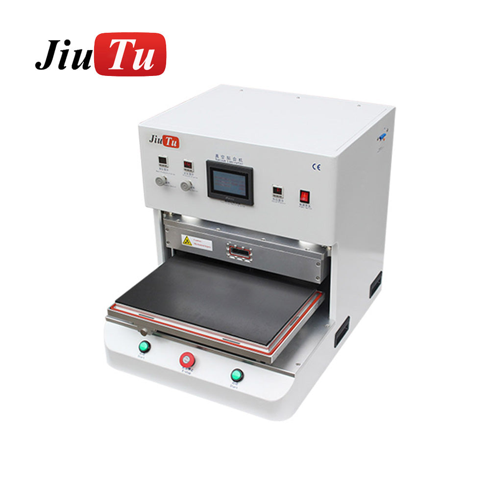
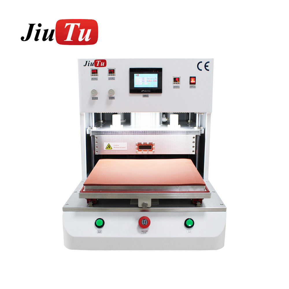
Workflow B: Temperature-assisted press bonding (hot-melt or controlled wet-out)
This workflow focuses on pressure profile control and thermal stability. It fits builds where temperature assistance improves wet-out or supports hot-melt style bonding. It also works well for process validation, where parameters must be controlled and repeatable.
Controlled ramps protect thin parts. Uniform heat reduces corner-to-corner variation. Fixture support prevents local tilt and thickness gradients.
Module match (risk control)
-
Newton rings: reduced by flatness, uniform pressure, and stable tooling.
-
Haze drift: reduced by stable temperature mapping and surface prep discipline.
Press bonding module
-
Product page: oca optical bonding machine
Workflow C: CCD alignment + vacuum lamination (tight bezel cosmetics, strict alignment)
This workflow targets repeatable positioning and reduced cosmetic scrap near bezels and printed borders. It is useful for builds where small offsets are visible or where panel geometry varies between lots.
CCD alignment increases repeatability. Vacuum lamination supports stable wet-out and bubble control. Fiducial-based acceptance tests make the result measurable.
Module match (risk control)
-
Misalignment: reduced by repeatability testing and vision alignment control.
-
Bezel cosmetics: improved by stable alignment and controlled first contact.
CCD lamination module
-
Product page: CCD Vacuum Laminating Machine
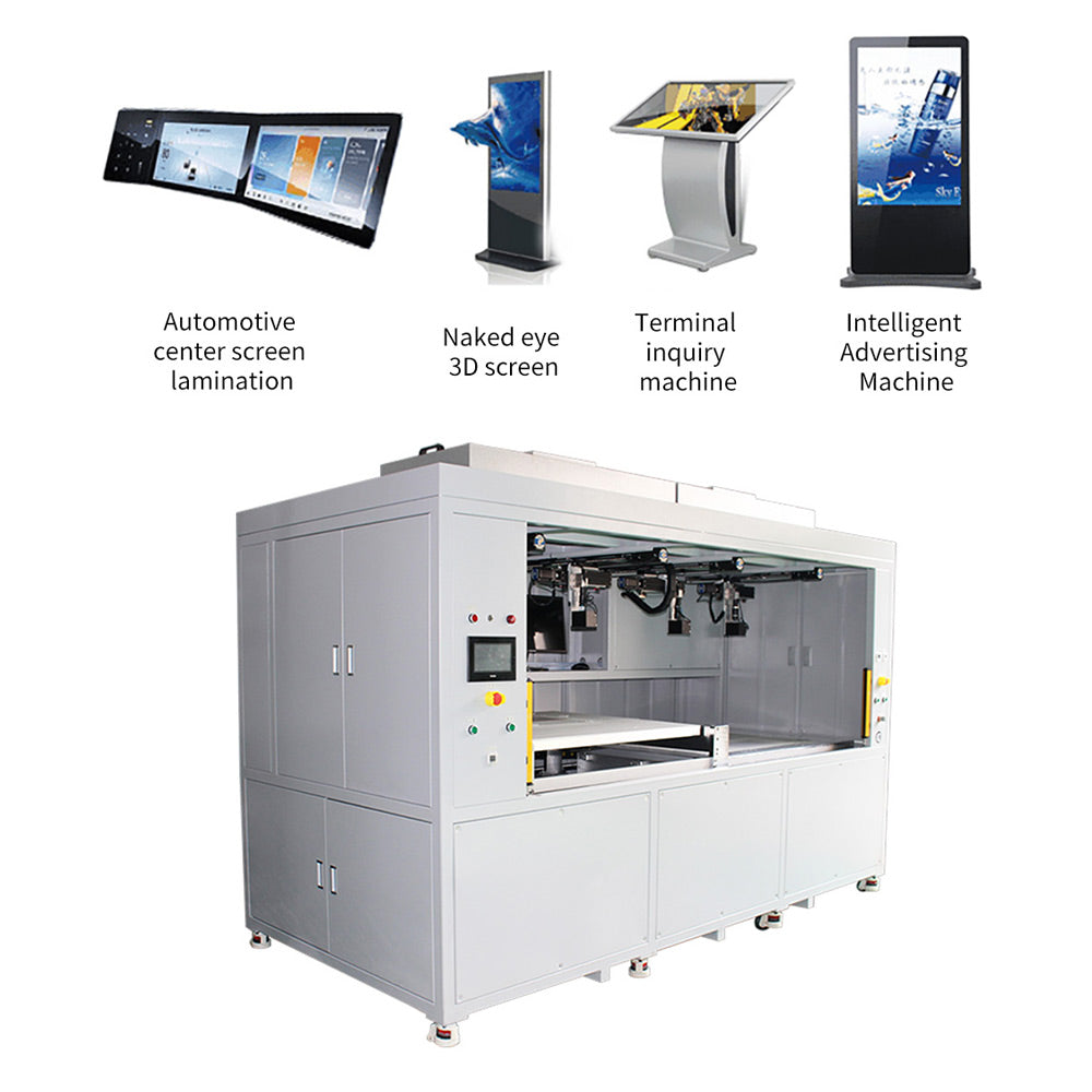
Workflow D: Large-area risk-control build (vacuum stability + flatness + stabilization)
Large-area stacks amplify bubble sensitivity and flatness demands. A conservative workflow emphasizes leak stability, fixture support, and a stabilization step. Strong acceptance clauses become more important because rework costs rise quickly with size.
In this workflow, vacuum leak-rate and pressure uniformity mapping should be tightened. Temperature uniformity mapping should be performed at operating setpoint. Rest-period re-checks should be non-negotiable.
Where to review on-site categories without losing focus
Equipment browsing is easier when grouped by process step: bonding/press, laminating, de-bubbling, and alignment. That approach prevents comparing tools that solve different problems.
For optical bonding-related equipment grouped together, the on-site category is a useful index:
For broader browsing across process steps and accessories, the full catalog can be used:
These links work well as internal references inside a purchasing guide because they keep browsing structured.
Maintenance and long-run consistency
A process that passes acceptance can still drift over months. Drift usually comes from seals, platen condition, and calibration habits.
Vacuum seals and leak stability
Seal wear increases leak rate and raises bubble return risk. A simple seal inspection schedule keeps the vacuum system stable. Periodic isolation tests can be logged to detect drift before yield drops.
Platen condition and pressure repeatability
Residue buildup and fixture wear can create local thickness changes. Those changes often show as rings or corner haze. Weekly platen inspection and cleaning routines reduce slow degradation.
CCD calibration discipline
CCD systems benefit from stable references and routine checks. A fiducial panel kept as a “golden sample” supports fast verification. A short calibration checklist helps keep repeatability stable across staffing changes.
FAQ
How should an adhesive bonding machine be qualified before purchase?
Qualification is strongest when it uses a defined stack, a defined fixture, and a repeatability run that includes a rest-period re-check. Leak isolation testing and pressure uniformity mapping should be documented. Those results translate cleanly into acceptance clauses.
What vacuum level should be written into acceptance terms?
Absolute pressure (kPa abs) reduces confusion. A practical clause includes pumpdown and leak-rate together, such as “reach ≤ ___ kPa abs within ___ seconds” and “pressure rise ≤ ___ kPa over ___ minutes after isolation.” The exact value should match adhesive behavior and panel geometry.
How can leak rate be verified without specialized equipment?
The isolation test is usually enough. Pump down to setpoint, isolate the chamber, and record pressure rise over a fixed time. Writing that method into acceptance terms prevents disputes and correlates with bubble return behavior.
How can pressure uniformity be measured in a realistic way?
Pressure-sensitive film works well for fast comparisons across zones. Thickness mapping with a compressible reference layer also works when a numeric result is preferred. The acceptance clause should specify the fixture, load, and mapping grid.
What temperature uniformity tolerance is realistic for optical bonding?
Many acceptance documents use ±2°C to ±5°C across the platen at a defined setpoint after stabilization. A multi-point mapping method keeps the clause objective. The setpoint should match the adhesive process rather than the maximum heater rating.
How should CCD alignment accuracy and repeatability be written into acceptance criteria?
A fiducial-based test panel keeps alignment measurable. Running 20–30 cycles and reporting mean error plus 3σ repeatability is common. The clause should also specify the measurement method and fiducial pattern.
Why do bubbles sometimes return after a clean-looking lamination?
Leak drift, release behavior, and edge air paths can allow micro-bubbles to grow after the cycle ends. Leak isolation testing often predicts this risk. A stabilization step, such as de-bubbling, can reduce failures after rest.
When does a de-bubbling module become essential?
De-bubbling becomes essential when micro-bubbles persist, bubble return appears after rest, or cosmetics must pass strict backlight inspection. It also reduces repeated handling, which lowers dust exposure risk.
How can Newton rings be reduced during equipment selection?
Platen flatness and pressure uniformity should be measured during trials. Fixture support points should prevent rocking and local tilt. Writing a uniformity clause into acceptance terms is one of the strongest safeguards.
What role does the adhesive bonding machine play in workflow stability?
The bonding station anchors repeatability when vacuum, pressure, temperature, and alignment remain predictable. When those controls drift, upstream and downstream steps cannot reliably compensate. That is why measurable acceptance tests are critical.
Summary and practical next steps
A “no mistakes” purchase comes from measurable stability, not from generic claims. Vacuum leak-rate, pressure uniformity, temperature mapping, and alignment repeatability are the four checks that most directly protect appearance and yield. When the workflow map is defined early, each equipment module can be matched to a defect risk instead of being selected by habit.
In that context, an adhesive bonding machine should be evaluated as the controlled center of a bonding cell. It delivers the most value when paired with disciplined preparation, stabilization, and inspection routines. The same logic also helps when expanding capacity, because the acceptance framework stays reusable across models and sites.
-
Create a one-page layer recipe and inspection standard, then use it for every trial.
-
Require four acceptance tests in writing: leak isolation, pressure uniformity mapping, temperature uniformity mapping, and alignment repeatability.
-
Choose a workflow configuration that includes stabilization and rest-period inspection, so the adhesive bonding machine stays inside a stable, repeatable process window.