Bubble-free bonding is decided by four cores—vacuum, pressure, heat, and alignment—plus a clean workflow that keeps surfaces “quiet.” In the field, most failures are not dramatic. Instead, a hold stage creeps, a platen loads unevenly, or the bond front runs too fast at the corners. This guide keeps the promise of a practical “trial-and-verify” method, and it stays anchored to the defects that matter: microbubbles, corner bubbles, haze, and Newton rings.
The 4 core indicators (what to look for in the machine body)
1) Vacuum: not the number, the hold
Vacuum specs look simple on paper. In practice, vacuum performance is a mix of chamber structure, sealing integrity, plumbing design, and control timing.
A good chamber evacuates evenly and holds without creeping back. That “hold” part is where yield quietly lives or dies. Many people watch the vacuum gauge during evacuation, then relax when it hits the target. However, the common surprise is this: the value looks pretty, but the hold floats. That float is a late-bubble incubator.
The machine-body features that usually separate “looks fine” from “stays fine” are mechanical:
-
Chamber rigidity and door geometry. A door that flexes or closes unevenly creates corner leaks. Meanwhile, a rigid enclosure stays consistent across cycles.
-
Seal design and serviceability. A gasket that wipes clean, seats cleanly, and replaces quickly helps vacuum performance stay stable over weeks. When seals are difficult to service, performance drifts gradually.
-
Evacuation path and port placement. On larger areas, air has to leave the interface evenly. Otherwise, one corner becomes a slow zone that turns into edge or corner bubbles later.
-
Valves and check behavior. In real production, small backflow during switching matters. So, clean valve timing and a reliable check path reduce “bounce” during hold.
There is also a “workflow truth” worth stating plainly. Dust and adhesive haze do not just affect optics. They also affect sealing. A dirty sealing surface behaves like a tiny leak, even when everything else is fine.
One key verification action: If only one metric gets checked, check the 30-second vacuum hold drift at the same point in the cycle.
Most common pitfall: treating “fast evacuation” as proof while the hold stage quietly creeps upward.
When vacuum hold slips, the inspection usually shows late microbubbles, especially near edges after a short rest.
2) Pressure: uniform contact beats brute force
Pressure is often described as a maximum number. Yet in optical bonding, pressure quality matters more than pressure peak. The goal is even contact and a calm bond front, not “as hard as possible.”
Machine-body features that control pressure quality are surprisingly physical:
-
Frame rigidity. A stiff frame resists flex under load. As a result, the platen stays parallel rather than bowing.
-
Platen flatness and support design. A flat platen helps keep adhesive thickness uniform. When thickness varies, Newton rings appear as interference fringes (often rainbow-like).
-
Actuation method (cylinder or servo). Pneumatic cylinder systems can work well when air supply is stable and ramp control is tuned. Servo systems can shape ramps more precisely and repeatably. Either can be excellent, but only if the ramp is controlled and consistent.
-
Floating mounts and leveling mechanisms. On larger work areas, even small tilt changes pressure distribution. Therefore, leveling points and balance adjustment matter more than many expect.
Pressure defects often appear where the bond front begins and ends. Corners are the classic pain point. Edge bubbles can look like dust at first glance, and that is why they waste time. Yet frequently the root cause is mechanical: the contact front advances too quickly at one side, trapping air.
A useful way to think about pressure is “front speed.” When pressure ramps too aggressively, the front “snaps.” Then air has no time to escape. A smoother ramp lets air migrate out as the front advances.
One key verification action: run two identical cycles and compare corners under strong light—any “one corner always worse” pattern suggests uneven pressure distribution or leveling.
Most common pitfall: increasing pressure to solve bubbles, then creating thicker-thinner zones that trigger Newton rings.
When pressure uniformity slips, the inspection usually shows corner bubbles, edge bubbles, and rings that repeat in the same zone.
3) Heat: even temperature, calm flow
Heat is not automatically good or bad. Instead, heat is a tool that changes adhesive flow and stress. Controlled warmth can widen the process window. Uneven heat shrinks it quickly.
The machine-body features that matter for heat are about the path heat takes:
-
Top-and-bottom heating vs single-side heating. Two-sided heating can reduce gradients across the stack. Single-side heating can work well, yet gradients become more noticeable as size increases.
-
Zoning and sensor placement. A stable setpoint only helps if the sensor reflects the interface reality. Otherwise, the display looks stable while the interface isn’t.
-
Thermal mass and insulation. A platen that holds temperature steadily reduces cycle-to-cycle variation. In contrast, a system that overshoots and hunts makes the bond front behave differently across runs.
Heat connects directly to haze and trapped air. When one area is warmer, adhesive wets earlier there. That early wetting pulls the bond front unevenly. Then the cooler side lags and traps microvoids. The result can look like contamination, but it’s often temperature-driven.
In the field, haze often gets blamed on materials too quickly. Meanwhile, the more common story is uneven flow. Haze, slight fogging, or “patchy clarity” usually tracks with uneven wetting and stress.
One key verification action: compare a cold start result with a steady-warm result using the same settings. If the look changes significantly, heat uniformity or control behavior needs attention.
Most common pitfall: tuning a recipe cold, then chasing “new defects” after warm-up.
When heat uniformity slips, the inspection usually shows haze, uneven clarity zones, and localized microbubbles that repeat in a warm/cool pattern.
4) Alignment + clean workflow: fewer touches, fewer surprises
Alignment gets treated like a human skill. Yet scalable alignment is a tooling decision. The best alignment method is the one that reduces handling and reduces exposure time.
Key machine-body and process features that support alignment are practical:
-
Datum strategy and fixture seating. A fixture that defines clear stops and seating surfaces reduces repositioning. Fewer reposition attempts mean fewer dust events.
-
Mechanical vs visual alignment. Visual alignment can be flexible for unusual jobs. However, fixture alignment scales better because it makes loading repeatable.
-
Platform leveling and repeatable clamping. If the work surface changes height or tilt between cycles, alignment and pressure distribution drift together.
-
Cleanliness-friendly loading. Short, simple loading steps matter. A calm workflow reduces the “open air” time between final clean and chamber seal.
This is where “field voice” is useful. Many people focus on vacuum and pressure while ignoring exposure time. Yet the most stubborn defects often begin as a tiny particle. Dust becomes a bubble seed. That bubble grows during hold, and the cycle gets blamed.
Another common moment: corner bubbles. They feel random. However, corner bubbles are often not random at all. They can come from fast front advance, poor edge support, or a fixture that allows slight lift at the corner.
One key verification action: measure the time from final clean to chamber seal, then watch whether defects spike when that time stretches.
Most common pitfall: treating cleanliness as “extra work,” then spending hours reworking bubbles seeded by dust.
When alignment and workflow slip, the inspection usually shows speck-triggered bubbles, cosmetic offsets, and corner instability that varies with handling.
30 minutes trial: the “verify fast” method
A practical trial should expose drift, not hide it. One perfect sample can happen even on weak setups. A short batch with simple checks tells the truth.
In many evaluations, this is the only question that matters: does the process stay the same for ten runs in a row? If yes, tuning becomes straightforward. If not, tuning becomes guesswork.
For equipment evaluation tied to bubble-free bonding, the trial below is designed to be realistic. It uses short holds, repeat cycles, and a rest check. It also avoids deep theory. Most importantly, it keeps attention on the four cores.
Even when the goal is general selection, a short trial aligns expectations around what a LCD bonding machine must do under real conditions.
Trial plan (30 minutes)
| Step | What to do | What to record | “Good” looks like | What it usually prevents |
|---|---|---|---|---|
| 1) Warm the system | Let heating stabilize if used | time to steady behavior | stable, no hunting | heat-driven haze drift |
| 2) Ten-cycle repeat run | Run 10 cycles, same settings | evacuation time each cycle | time stays close run-to-run | random bubble scatter |
| 3) 30-second hold check | Hold vacuum at same stage | drift direction + size | minimal creep during hold | late microbubbles |
| 4) Corner comparison | Inspect corners each run | corner location patterns | no “same corner always worse” | corner bubbles / edge traps |
| 5) Ring map check | View under angled light | ring location repeat | rings don’t repeat in one zone | thickness-driven rings |
| 6) Rest-and-recheck | Wait briefly, re-inspect | bubble growth after rest | no new microbubbles appear | “passes now, fails later” |
What to ignore during the trial
It helps to ignore marketing-style “maximum pressure” discussions unless a specific stack truly needs it. Similarly, “fastest cycle time” rarely matters in early selection.
Instead, stability under a short batch matters most. If the ten-cycle run looks consistent, optimization becomes a second step.
Common defects → the machine features that usually fix them
Defects are often easier than specs. A defect points to a specific failure mode. That failure mode points back to a machine feature.
The table below keeps selection aligned to the title. It answers: which key feature actually matters for bubble-free results?
| Defect pattern | What it usually means | What to check in the machine | Fast trial clue |
|---|---|---|---|
| Microbubbles that appear later | air returns during hold or bond front traps microvoids | vacuum hold integrity, sealing quality, valve timing | 30-second hold drift shows creep |
| Corner bubbles / edge bubbles | contact front moves too fast or loads unevenly | ramp control, leveling, fixture edge support | same corner repeats across runs |
| Haze / foggy zones | uneven wetting or thermal gradient stress | top/bottom heat uniformity, sensor placement | cold vs warm run looks different |
| Newton rings | thickness variation across area | platen flatness, rigidity, balance adjustment | rings repeat in the same zone |
A practical note helps here. Many problems look like contamination. However, “contamination-like” defects often trace back to uneven flow, uneven pressure, or uneven temperature. That is why the trial checks focus on repeat patterns rather than one-off marks.
Equipment role examples (card-style, matched to key features)
The examples below are selected from the LCD repair equipment lineup shown under the LCD Repair Machine category.
They are presented as station roles rather than product blurbs. The goal is selection clarity: who uses it, which core it supports, which defect it helps reduce, and what to verify in a trial.
To keep the guide grounded, the feature notes follow the specifications and descriptions on the respective product pages.
A short reminder belongs here as well: a LCD bonding machine rarely operates alone in a real workflow. In practice, lamination and post-lamination defoaming often work as a pair when cosmetic targets are strict.
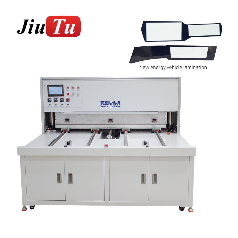
Example A — 16-inch class vacuum laminator (compact lamination station)
Product: 16 Inch Vacuum Laminator Screen Repair LCD OCA Lamination Machine for iPad/Tablets
Typical use scenario: phone and tablet refurbishment; under-16-inch screens; frequent model changes; batch loading on a plate when fixtures allow.
Strongest key feature: vacuum lamination with practical external utilities (vacuum pump + air compressor), which supports stronger evacuation and consistent pressing behavior.
Typical defects it helps reduce: scattered bubbles from poor evacuation, plus edge bubbles when ramps and fixtures are tuned.
One must-verify trial action: run the 10-cycle test and record evacuation time; inconsistent timing often signals sealing or plumbing issues before tuning even starts.

Compact vacuum laminators are common for high-mix refurbishment work where changeover speed matters.
Example B — TP+LCM OCA laminating platform (process-controlled lamination for wider stacks)
Product: TP+LCM OCA Laminating Machine
Typical use scenario: larger work area (380 × 580 mm); G+G bonding processes; mixed panel work where consistent parameters matter more than speed.
Strongest key feature: controlled pressure range plus upper-and-lower heating (up to 100°C), which supports more even wetting across the work area.
Typical defects it helps reduce: haze from uneven wetting and rings tied to thickness drift, especially when thermal uniformity and pressure distribution stay consistent.
One must-verify trial action: compare a cold-start run to a steady-warm run; a big optical change often points to heat uniformity or control behavior.

Platforms in this class are often chosen for stable parameters across wider work areas.
Example C — TP+LCM vacuum bonding platform (large-format bonding with leveling/balance emphasis)
Product: TP+LCM Vacuum Bonding Machine
Typical use scenario: larger-format lamination (35/55/65/85 inch class referenced); applications include mobile, hot pressing lamination, car navigation, and lab R&D use cases.
Strongest key feature: up-and-down heating up to 100°C plus a working platform balance adjustment function, which helps keep pressure distribution and thickness more uniform across large areas.
Typical defects it helps reduce: one-side rings and corner voids driven by tilt, plus haze linked to thermal gradients across wide spans.
One must-verify trial action: inspect whether a “bad zone” stays in the same location across multiple cycles; a repeating zone often points to leveling, platen support, or fixture issues.
Large-format platforms make small flatness and leveling errors visible fast.
Example D — High-pressure bubble remover autoclave (post-lamination defoaming station)
Product: LCD Vacuum Bubble Remover Machine
Typical use scenario: post-lamination finishing for electronics and optoelectronics; used after vacuum lamination with OCA/SCA to remove residual bubbles; chamber-based pressure-and-heat defoaming.
Strongest key feature: segmented high-pressure defoaming with adjustable temperature and pressure, designed to reduce microbubbles after lamination rather than replacing the lamination step.
Typical defects it helps reduce: late microbubbles and “fine peppering” that appears after resting, especially when lamination is close-but-not-perfect.
One must-verify trial action: run a rest-and-recheck inspection after defoaming; microbubble growth after rest indicates either incomplete defoaming or upstream hold/front issues.
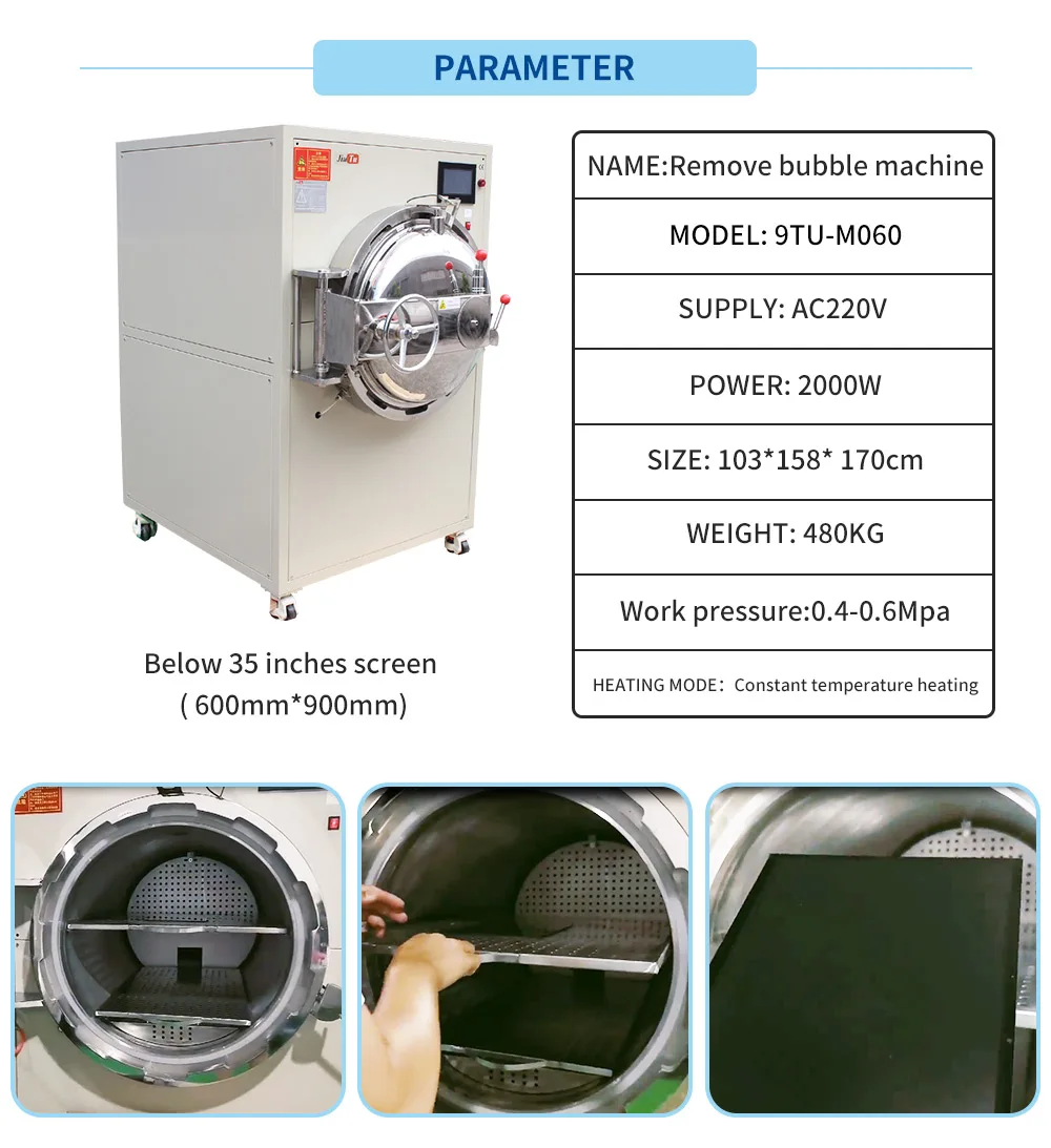
Autoclave-style defoaming is a common finishing step when microbubbles remain after lamination.
The “pitfall sweep”: how to rule out the usual traps
This section is intentionally short. It collects the field traps that waste the most time.
Pitfall 1: vacuum looks good until hold
A strong evacuation number can hide hold creep. That creep feeds late bubbles.
The quick fix is not a new adhesive. Instead, it is a hold test, a gasket wipe, and a repeat run. If the hold still creeps, sealing and valve timing deserve attention.
Pitfall 2: pressure increased to “push out” bubbles
Higher force can trap air at corners if the front snaps into place. It can also worsen rings if thickness shifts.
A calmer ramp usually beats extra force. Meanwhile, better edge support often beats both.
Pitfall 3: heat used as a shortcut
Heat can improve wetting. Yet uneven heat creates uneven flow fronts. That unevenness turns into haze or localized bubbles.
Cold/warm comparison catches this quickly. If the look changes a lot, thermal uniformity matters more than raw temperature.
Pitfall 4: alignment treated like “hands”
When alignment depends on repeated repositioning, exposure time increases. Dust arrives. Then bubbles seed around particles.
Fixtures and defined datums reduce touches. Less handling often produces the fastest yield improvement.
FAQ (selection questions that come up in real evaluations)
What single check is most informative during selection?
The 30-second vacuum hold drift check is the fastest “truth test.” It often predicts late microbubbles better than any spec sheet.
Why do corner bubbles appear even when surfaces look clean?
Corner bubbles often form when the bond front advances too fast at the edges. Pressure ramps, leveling, and edge support matter.
What causes Newton rings in bonding?
Newton rings usually come from thickness variation. Platen flatness, rigidity, and leveling often drive that variation.
Does higher pressure always reduce bubbles?
Not always. Higher pressure can increase stress and trap air if ramp control is poor. Uniform pressure and smooth ramps matter more.
When does top-and-bottom heating matter most?
It matters when gradients cause uneven wetting across the area. Larger formats and thicker stacks tend to show this more clearly.
Why does a recipe behave differently after hours of running?
Thermal steady state changes how the platen holds temperature. Therefore, cold-start tuning can drift once the machine warms up.
Is post-lamination defoaming always required?
Not always. Yet when microbubbles appear after resting, a defoaming step often stabilizes final appearance—especially for stricter cosmetic targets.
Which defects most often signal fixture issues?
Repeating rings, one-side haze, or “always the same corner” bubbles usually point toward fixture seating, edge support, or leveling issues.
Trial checklist (copy/paste for evaluation notes)
-
30-second vacuum hold drift: record creep during hold at the same cycle stage.
-
10-cycle evacuation time: log timing for each cycle; watch for drift.
-
Cold vs warm comparison: run one early, one after steady behavior.
-
Corner repeat pattern: note whether one corner stays worse.
-
Ring map: record ring location under angled light.
-
Rest-and-recheck: inspect again after a short rest for late bubbles.
Summary and three actionable next steps
A bubble-free process comes from four cores—vacuum, pressure, heat, and alignment—supported by a clean workflow. Vacuum must hold, pressure must load evenly, heat must stay uniform, and alignment must reduce handling. When those pieces line up, defects stop “moving around” and tuning becomes practical.
Actionable next steps:
-
Run the 30-minute trial and keep the notes defect-based rather than spec-based.
-
Treat fixtures as a core tool, especially for edge support and repeatable seating.
-
Add post-lamination defoaming when microbubbles show up after resting.
With that approach, selecting a LCD bonding machine becomes a structured decision instead of a guess.