
Clean optical bonding is never a single “press” action. Instead, perfect bonding comes from controlled surfaces, stable alignment, and predictable air removal. For that reason, a glass laminating machine matters most when it behaves like a process platform, not a simple tool. Strong bonding improves clarity, reduces rework, and stabilizes long-term reliability. This guide turns bonding concepts into shop-floor decisions, with parameter windows, checklists, and practical troubleshooting.
What “perfect bonding” really means
In practice, “perfect bonding” describes an interface that behaves like one optical body. That outcome requires uniform contact, stable adhesion, and controlled thickness across the active area. As a result, the stack shows fewer reflections, fewer bubbles, and less edge lift after aging.
At the same time, perfect bonding is measurable, not emotional. Clear targets like bubble limits, haze thresholds, and edge integrity make decisions faster. Consequently, process work shifts from debate to verification.
The bonding outcomes worth targeting
To begin with, these outcomes usually track yield and field reliability:
-
Uniform wet-out across the full bonded region
-
Low haze and minimal streaking under angled inspection light
-
No visible voids in the active display zone
-
Clean edges with stable adhesion after temperature cycling
-
Predictable rework behavior when rework is allowed
Meanwhile, each outcome maps to controllable inputs. Cleanliness affects haze and voids, while pressure ramps affect wet-out. Because of that, the best documentation starts with outcomes, then assigns control points.
Common defects that break optical quality
Importantly, many defects look similar but come from different sources:
-
Bubbles and voids: trapped air, moisture outgassing, or early contact
-
Haze and streaks: contamination films, adhesive shear, or surface texture mismatch
-
Newton rings: gap non-uniformity, curvature mismatch, or uneven pressure distribution
-
Edge lift: low surface energy, insufficient dwell, or stress concentration at corners
-
Misalignment: fixture drift, camera calibration offsets, or substrate slippage
However, defects often cluster by “signature.” A line of bubbles hints at a tack path, while corner voids hint at edge support. Therefore, a good guide must connect “what appears” to “what to check first.”
How glass lamination systems create a stable interface
In general, lamination succeeds when air leaves before the interface seals. Vacuum helps, but vacuum alone does not guarantee wet-out. Instead, pressure timing and surface cleanliness decide whether adhesive flows into micro-texture. As a result, process recipes must define ramps and dwell, not only peak force.
Additionally, alignment stability matters more as size increases. Substrate flex under vacuum can shift alignment if fixtures lack support. Therefore, platform stiffness, chuck design, and balancing functions become production-level variables.
Core functions inside most lamination platforms
Typically, a lamination platform combines several modules:
-
Fixturing and alignment: mechanical references, vacuum chucks, or camera alignment
-
Air removal: chamber vacuum, staged vacuum, or local vacuum zones
-
Pressure application: platen press, diaphragm press, or controlled nip rollers
-
Thermal control: heated plates, controlled warm-up, and stability holds
-
Recipe control: setpoints, ramps, dwell timing, and alarms for drift
Notably, module interaction creates hidden failure modes. A strong vacuum pull can warp thin glass if supports are uneven. Likewise, fast pressure ramps can trap air even with good vacuum. Consequently, tuning must consider the full system, not isolated knobs.
Why pressure ramps beat “more pressure” thinking
Often, peak pressure gets blamed or praised incorrectly. In reality, the ramp controls whether air escapes ahead of the wet-out front. A slower ramp allows adhesive to flow and equalize stress. As a result, rings, streaks, and voids drop without raising pressure.
On the other hand, ramps that are too slow can invite dust deposition in uncontrolled environments. That risk rises when the process pauses mid-contact. Therefore, ramp strategies must match the cleanliness level and handling time.
Where temperature helps, and where it hurts
In many stacks, mild heating reduces viscosity and improves flow. That change can speed wet-out and reduce micro-voids. Still, heating also increases outgassing if materials carry moisture or solvents. Consequently, heating belongs in the recipe only after storage and drying controls are stable.
Materials and stack design that protect clarity
To start, adhesive selection sets the bonding “behavior.” Some adhesives wet quickly but show higher shrink stress later. Other adhesives wet slowly but remain stable under heat cycling. As a result, material choice should follow application stress, not only first-look clarity.
Meanwhile, glass coatings and textures can change everything. Anti-glare surfaces increase micro-texture, so adhesive must fill tiny valleys. Low-energy coatings resist wetting, so surface activation may be necessary. Therefore, stack design must consider surface energy and texture, not only thickness.
OCA film vs LOCA in plain terms
Broadly, two optical bonding approaches dominate:
-
OCA (optically clear adhesive film): consistent thickness, clean handling, stable optical uniformity
-
LOCA (liquid optically clear adhesive): better gap filling, useful for curvature and unevenness, cure control becomes critical
In practice, OCA film helps when thickness tolerance matters and surfaces are flat. Conversely, LOCA helps when the stack contains gaps or curvature. Because of that, the “right” choice depends on geometry and inspection requirements, not preference.
Surface preparation that reduces bubbles and haze
First, surface cleanliness must remove particles and oily films. A particle can create a tenting point, which becomes a void under pressure. Likewise, a thin residue film can create haze even when bubbles are absent. Therefore, cleaning methods must be validated, not assumed.
Second, static control lowers random defects. Film liners and polymer sheets can attract dust through static charge. As a result, ionized air and grounded handling reduce the defect floor.
Finally, moisture control prevents late bubble growth. Adhesives and porous coatings can absorb moisture during storage. Under heat or pressure, that moisture becomes gas and forms microbubbles. Consequently, storage temperature, humidity, and exposure time belong in process documentation.
A practical bonding flow
In a well-run line, bonding follows a repeatable sequence. Small steps reduce handling risk and create stable timing. As a result, yield becomes predictable and training becomes easier.
Below is a practical flow designed for clarity and robustness. Each step includes “what to control” and “what to confirm.” Where helpful, this related internal reference expands on bubble control during OCA lamination: LCD Laminating Machine Guide: Cleaner, Bubble-Free OCA Lamination.
Step 1: Stabilize the environment and materials
At the beginning, confirm temperature and humidity stability. Rapid swings cause condensation, static shifts, and adhesive behavior drift. Because of that, many lines set a stable window and document it.
Next, stage materials to reach equilibrium. Cold film moved into a warm room can trap moisture on the surface. Similarly, warm glass moved into a cooler zone can pull moisture from air. Therefore, staging time is a real parameter, not an afterthought.
Step 2: Clean and dry with a validated sequence
Afterward, clean glass with a method that removes both particles and oily residues. Water marks and detergent films can create haze that looks like adhesive issues. Consequently, the last rinse and drying method deserve special attention.
Then, verify cleanliness with a simple routine. Bright angled light reveals particles, while a surface energy check reveals poor wetting. As a result, checks catch issues before lamination locks them in.
Step 3: Prepare adhesive with predictable handling
For OCA film, cut and place without stretching. Stretch creates thickness variation and stress patterns that show later as optical non-uniformity. Therefore, film handling rules should include liner peel angles, peel speed, and maximum exposure time.
For LOCA, manage viscosity and pot life carefully. Mixed liquid that sits too long can trap bubbles and cure unevenly. Because of that, dosing and degassing steps must be written down clearly.
Step 4: Align, tack, and close contact in a controlled way
At this stage, alignment tools must prevent slippage. Mechanical stops reduce drift, while camera alignment reduces bias across formats. Consequently, alignment belongs before any full-area contact begins.
Then, use a tack strategy that avoids trapping air. Gentle edge tacking can define a controlled wet-out front. On the other hand, full-area tacking too early seals air inside. Therefore, tack timing should be part of the recipe.
Step 5: Vacuum, ramp pressure, and hold for wet-out
Now, vacuum must stabilize before contact seals. A short vacuum time can leave pockets that become voids later. As a result, recipes often include a vacuum stabilize period plus a confirmation check.
Next, ramp pressure gradually. A controlled ramp helps adhesive flow, fill texture, and equalize thickness. Therefore, ramp speed often matters more than peak pressure.
Finally, hold pressure long enough for the interface to relax. Adhesive can continue flowing under steady load, especially on textured surfaces. Consequently, dwell time is a yield lever, not a nuisance.
Step 6: Post-process debubbling when the stack needs it
In many production stacks, microbubbles remain after lamination. Textured coatings, edges, and curvature increase this risk. Therefore, a post-process debubbling stage can stabilize clarity and reduce rework.
On Jiutu’s optical bonding line, an example vacuum laminator lists heating up to 100 °C and high mechanical pressure capability, with a stated lamination area around 600×900 mm.
That kind of platform can pair with a dedicated bubble removal stage for stubborn microbubbles.
Process window table
In practice, parameter windows vary by adhesive, glass thickness, and surface texture. Still, “starting windows” help teams converge faster during validation. Because of that, the table below provides safe starting ranges, plus adjustment logic.
Note: Values below are starting ranges, meant for process development and verification.
| Stack type | Vacuum target (starting range) | Vacuum stabilize | Pressure ramp | Peak pressure | Dwell under pressure | Plate temp (if used) | Post-debubble |
|---|---|---|---|---|---|---|---|
| Flat glass + OCA film + module | High vacuum, stable | 20–60 s | 15–60 s ramp | Medium | 30–120 s | 25–60 °C | Optional; use if microbubbles persist |
| Textured AG glass + OCA film | High vacuum, stable | 30–90 s | 30–90 s ramp | Medium | 60–180 s | 40–70 °C | Recommended; helps edge and texture voids |
| Large panel (kiosk/TV) + OCA | High vacuum, stable | 60–180 s | 60–180 s ramp | Medium-high | 120–300 s | 30–60 °C | Often recommended for uniformity |
| Curved glass + LOCA | Vacuum supports degassing | 30–120 s | Slow, staged | Low-medium | Staged holds | 25–50 °C | Depends on cure and geometry |
How to adjust without chasing noise
First, adjust only one lever at a time. Simultaneous changes hide the true cause of improvements. As a result, debugging time grows and confidence drops.
Second, use defect signatures to choose the lever. Edge microbubbles usually respond to dwell and debubbling. Newton rings often respond to flatness and pressure distribution. Therefore, “symptom → lever” thinking saves time.
Inspection and acceptance criteria
Inspection becomes meaningful when criteria are written clearly. Loose terms like “looks okay” invite inconsistent sorting. Consequently, acceptance criteria should include zones, size categories, and lighting methods.
Lighting methods that reveal different defects
In general, three lighting setups catch most defects:
-
Backlight or transmitted light: reveals bubbles, voids, and streaks over active area
-
Low-angle grazing light: highlights particles, haze films, and surface scratches
-
Cross-polarized inspection (when applicable): reveals stress patterns and non-uniform thickness
Meanwhile, repeatability matters more than perfect equipment. A consistent lamp distance and angle makes trend tracking possible. Because of that, inspection jigs can improve yield even without fancy optics.
Practical, zone-based acceptance templates
Rather than forcing one universal limit, a zone-based template works better:
-
Zone A (active area): strict limits for bubbles and haze
-
Zone B (border area): moderate limits, especially near bezels
-
Zone C (hidden edge): practical limits focused on adhesion and seal
Additionally, define size bins for bubbles. For example, “microbubble,” “small bubble,” and “large bubble” categories reduce debate. Consequently, operators can apply rules quickly and consistently.
Adhesion and edge integrity checks
Optical clarity is not the only goal. Edges must resist lift after thermal and humidity stress. Because of that, simple edge checks belong in the routine.
Common checks include a visual edge scan and a controlled peel test on witness samples. In some lines, accelerated aging tests like temperature cycling or damp heat confirm long-term stability. Therefore, acceptance criteria should include an aging plan, not only day-one appearance.
Two real production scenarios
Real scenarios expose the “hidden variables” that generic advice misses. The cases below show symptom patterns, top causes, and fast verification steps. As a result, troubleshooting becomes a repeatable method.
Scenario 1: 10.1" industrial HMI shows edge microbubbles after 24 hours
At first inspection, the bonded area looks clear. After a day, microbubbles appear along one edge and corners. That pattern often indicates slow outgassing or edge wet-out limitations.
Most likely causes (ranked):
-
Moisture pickup in adhesive or stack during staging
-
Edge support weakness causing uneven pressure near corners
-
Dwell time too short for texture fill and stress relaxation
Fast verification steps:
-
Compare parts laminated early versus late in the shift
-
Check humidity logs and exposure time for adhesive liners
-
Inspect platen contact marks for edge pressure uniformity
Adjustments that usually help:
-
Add a short, controlled post-debubble stage for microbubbles
-
Increase dwell time before release, focusing on edge wet-out
-
Improve edge support shims or compliant layers near corners
When a bubble removal stage is used, Jiutu’s bubble remover listings highlight a high-pressure debubbling concept with heating up to 80 °C for air bubble removal applications.
Scenario 2: 21.5" kiosk panel shows Newton rings and faint streaks under angled light
Under backlight, the panel appears acceptable. Under grazing light, rings appear near the center and streaks appear along one axis. That signature often points to gap non-uniformity and shear during wet-out.
Most likely causes (ranked):
-
Flatness mismatch between glass and underlying module
-
Pressure distribution non-uniformity across the platen
-
Ramp speed too fast, creating directional shear marks
Fast verification steps:
-
Measure flatness using a straightedge and feeler gauge points
-
Compare ring location to support points and vacuum chuck layout
-
Run a trial with slower pressure ramp, holding alignment constant
Adjustments that usually help:
-
Improve fixture support, especially over large unsupported spans
-
Add a compliant layer to smooth pressure distribution
-
Slow the ramp and extend the dwell to reduce shear artifacts
For larger vacuum laminator platforms, Jiutu’s vacuum laminator description lists a stated lamination area around 600×900 mm and a process description that includes heating and vacuum extraction before lamination.
Troubleshooting matrix
Troubleshooting improves when defects map to checks and levers. The matrix below prioritizes “fast checks” before deep teardown. Consequently, downtime decreases and learning accumulates.
| Defect | High-probability causes | Fastest checks | Process levers | Prevention habits |
|---|---|---|---|---|
| Edge microbubbles | Moisture, weak edge pressure, short dwell | Compare early/late shift, check humidity, inspect edge contact | Extend dwell, add debubble, adjust edge support | Control exposure time, standardize edge support |
| Random bubbles across area | Dust, static, early sealing | Inspect under grazing light, check ionizer, check tack method | Improve cleaning, change tack path, increase vacuum stabilize | Ground handling, validate cleaning, reduce open time |
| Haze or film | Residue, liner contamination, chemistry film | Wipe test on witness glass, compare batches, check rinse | Change cleaning step, add final rinse, adjust handling | Standardize chemistry, replace cloth schedule |
| Newton rings | Gap non-uniformity, curvature mismatch, pressure non-uniformity | Flatness checks, support mapping, trial compliant layer | Fixture redesign, compliant layer, pressure distribution tuning | Flatness monitoring, platen mapping routine |
| Streaks (directional) | Shear during ramp, slip, roller marks | Check ramp logs, inspect slip points, slow trial | Slow ramp, improve clamping, adjust contact strategy | Document ramp windows, verify fixture friction |
| Misalignment | Calibration drift, fixture wear, substrate shift | Check alignment marks, verify camera calibration | Recalibrate CCD, update fixtures, adjust vacuum pull | Calibration schedule, fixture wear tracking |
| Edge lift after aging | Low surface energy, stress at corners, insufficient dwell | Surface energy check, corner inspection, peel witness | Surface activation, longer dwell, corner radius update | Activation verification, corner stress reduction |
A quick “root cause discipline” checklist
Before major changes, apply a simple discipline:
-
Confirm the defect signature and zone pattern first
-
Change one lever and record the result
-
Save photos and settings in a batch log
-
Re-run the same stack to confirm repeatability
As a result, knowledge becomes transferable across shifts and sites.
Line pairing and equipment matching
A lamination line rarely works as a single machine. Upstream film prep affects wet-out, while downstream debubbling stabilizes clarity. Because of that, line pairing decisions often beat micro-tuning in impact.
For category navigation across the store’s equipment families, this hub helps compare options without jumping outside the catalog: All Collections.
Pairing 1: Vacuum laminator + bubble removal stage
In many stacks, a vacuum laminator forms the initial bond. A dedicated bubble removal unit then collapses residual microbubbles under heat and pressure. Consequently, the final surface looks cleaner and remains stable after short aging.
Jiutu’s vacuum laminator description includes heating capability up to 100 °C and a stated maximum pressure capability.
Meanwhile, the bubble removal listing describes high-pressure debubbling with heating up to 80 °C for air bubble removal applications.  Figure 1: A vacuum laminator supports staged vacuum and controlled contact for large glass stacks.
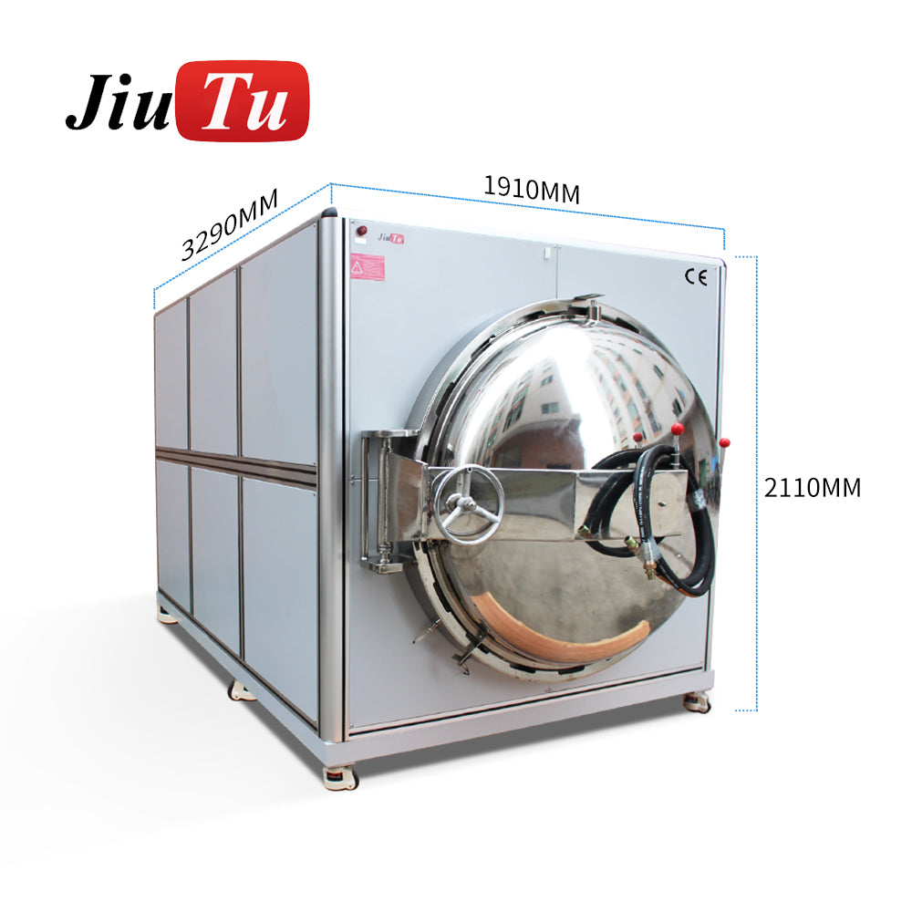 Figure 2: A post-process debubbling stage targets microbubbles that survive initial lamination.
Pairing 2: CCD alignment + cleaner airflow for precision stacks
Large or high-precision stacks benefit from better alignment and cleaner handling. Camera alignment can reduce skew and offset drift across formats. Likewise, cleaner airflow reduces dust-driven voids. Consequently, this pairing often increases yield more than pressure changes.
On Jiutu’s CCD/FFU laminating equipment page, the listing describes controlled working conditions and industrial air supply requirements.
 Figure 3: CCD alignment and cleaner airflow support repeatability when tolerances tighten.
Pairing 3: Film-to-film or flexible-to-rigid prep before final bonding
For many stacks, film preparation decides final clarity. Wrinkles, stretch, and trapped air start here, not at final pressing. Therefore, a stable film laminating stage improves final bonding outcomes.
Jiutu’s soft-to-soft laminating listing describes a machine designed for laminating flexible films to rigid or flexible substrates.
 Figure 4: Film preparation reduces downstream defects by stabilizing the adhesive layer early.
Preventive maintenance and calibration checklist
Maintenance is process control in disguise. Leaks, drift, and contamination slowly raise defect rates. Because of that, a simple checklist protects yield more than heroic troubleshooting.
Daily checks (fast, high value)
-
Confirm vacuum stability with a short leak-down check
-
Clean contact surfaces and remove adhesive residue safely
-
Verify ionizer function and grounding continuity
-
Inspect filters and airflow direction for dust control
Additionally, log abnormalities immediately. Small notes reveal patterns across weeks. As a result, preventive changes become data-driven.
Weekly checks (repeatability protection)
-
Verify platen flatness at key points using a simple mapping routine
-
Check pressure uniformity using a uniform witness method
-
Confirm camera alignment calibration on a standard reference coupon
-
Inspect fixtures for wear, burrs, and drift in locating features
For CCD-based equipment, drift often appears gradually. Therefore, a weekly verification catches bias before it becomes scrap.
Monthly checks (system health)
-
Inspect vacuum seals, gaskets, and hose connections for micro leaks
-
Verify heating uniformity across the plate and document offsets
-
Check sensor drift and recalibrate critical readings
-
Review batch logs for slow shifts in defect signatures
In addition, schedule deep cleaning of ducts and enclosed areas. Dust accumulates where it cannot be seen easily. Consequently, monthly routines prevent invisible contamination spikes.
Selection framework for the right configuration
Selection becomes easier when it starts with stack needs, then adds production needs. That sequence avoids overbuying features that do not affect outcomes. As a result, the final configuration matches real constraints.
For category browsing and core options, this collection acts as the anchor for the target equipment family: glass laminating machine.
Step 1: Define the stack requirements
Start with the physical stack:
-
Glass size, thickness, and stiffness
-
Flat or curved geometry, plus allowable curvature tolerance
-
Adhesive type and thickness range (OCA film, LOCA, hot-melt options)
-
Coatings, textures, and surface energy behavior
-
Optical acceptance limits and aging reliability goals
Next, define alignment tolerances. Tight bezels and large panels increase sensitivity. Therefore, alignment capability belongs in the requirements list.
Step 2: Define production requirements
Then, define production behavior:
-
Throughput targets and changeover frequency
-
SKU variety and fixture strategy
-
Recipe management, traceability, and parameter logging needs
-
Utility constraints like air supply, power, and footprint
-
Maintenance access and wear-part logistics
In addition, consider training time. Simple, consistent workflows beat clever but fragile workflows. Consequently, automation and recipe locks can matter as much as raw capability.
Step 3: Match the configuration to the application scenario
Scenario A: Industrial HMI and medium panels
Stable alignment and controlled ramps matter most. A vacuum laminator plus optional debubbling often covers these stacks.
Scenario B: Large kiosk and signage stacks
Platen flatness, fixture support, and pressure distribution dominate. Post-process debubbling often stabilizes microbubbles.
Scenario C: Curved automotive stacks
Gap filling and stress control become the focus. LOCA processes may fit better, with careful cure and thermal control. Therefore, geometry drives the tool choice.
For equipment category reference during shortlist building, the same anchor page remains the most direct guide: glass laminating machine.
Glossary
Wet-out: Adhesive spreads and fills micro-texture until the interface becomes uniform.
Ramp: Controlled change of pressure or vacuum over time to avoid sealing air.
Dwell: Hold time under stable pressure, allowing flow and stress relaxation.
Newton rings: Optical interference patterns from non-uniform gaps between layers.
Haze: Scattered light that reduces contrast, often caused by residues or micro-texture.
Debubbling: Post-process stage that collapses microbubbles using heat and pressure.
Surface energy: How easily a surface wets; low energy often resists adhesion.
CCD alignment: Camera-based alignment system for repeatable position control.
FAQ
What makes bubbles appear even when vacuum is used?
Often, early contact seals air before vacuum stabilizes. Moisture outgassing can also create late microbubbles. Therefore, vacuum stabilize time and storage controls both matter.
Why do microbubbles show up hours later?
In many stacks, moisture and dissolved gases release slowly after lamination. Edge areas also wet-out more slowly under uneven pressure. Consequently, debubbling and dwell tuning can reduce delayed bubbles.
How can Newton rings be reduced without changing glass?
First, improve support to reduce gap variation under the center area. Next, tune pressure distribution and use compliant layers where appropriate. As a result, the interface becomes more uniform.
What causes directional streaks under angled light?
Directional streaks often trace to shear during fast ramps or small slippage events. Fixture friction and tack strategy can also drive the direction. Therefore, ramp control and anti-slip alignment help.
When does a debubbling stage add the most value?
Debubbling helps when textures trap micro air pockets or when panels are large. Edge microbubbles often respond well to post-process pressure and heat.
Which checks catch issues before lamination locks them in?
Grazing light reveals dust and residue films early. A simple surface energy check can predict poor wetting on coated glass. Consequently, pre-lamination checks save the most scrap.
How should film adhesives be staged before use?
Stable temperature and controlled humidity reduce moisture pickup and static behavior. Exposure time outside packaging also matters. Therefore, staging rules should be part of the work instruction.
What is the simplest way to improve repeatability across shifts?
Lock recipes and document ramps, dwell, and staging time in one sheet. Then, use a small batch log with photos and settings. As a result, drift becomes visible quickly.
Summary and three actionable recommendations
Overall, perfect bonding comes from stable surfaces, controlled air removal, and predictable wet-out. Strong results follow when ramps, dwell, and debubbling match the stack’s geometry and texture. Because of that, the best improvements usually come from line pairing, inspection discipline, and preventive calibration. In the end, a glass laminating machine delivers consistent clarity only when the surrounding workflow stays controlled.
-
First, build a one-page recipe with ramps, dwell, staging time, and inspection lighting rules.
-
Next, add a defect log that records zone patterns, photos, and one-change-at-a-time trials.
-
Finally, schedule weekly flatness and calibration checks to prevent slow drift and surprise scrap.