A layered display problem usually starts with something small. One film edge curls during peeling. A thin dust line stays near the black border. A corner bubble appears 30 minutes after the panel looked clean. In display stack assembly, these small signs matter more than a machine specification sheet. A Multi-Layer Screen Bonder should be chosen by stack behavior, not by the idea that more pressure or more functions will solve every defect.
This field is still not too crowded. Many articles only talk about machine size, pressure range, and heating. However, real bonding work is more practical. First, look at the visible problem. Then find the cause. After that, judge whether alignment, fixture support, adhesive choice, vacuum lamination, or bubble removal is the next step. That is the cleaner way to think about multi-layer screen bonding.
Basic Principle: Why Multi-Layer Display Bonding Is Hard to Keep Stable
Optical bonding sounds simple at first. Several display layers need to sit together with less air between them. Cover glass, touch sensor, LCD, polarizer, OCA film, OCR adhesive, protective film, and functional coating all need clean contact. When the stack is stable, the screen usually looks clearer and feels more solid.
However, the real process is not just pressing layers together. Each surface reacts differently. Glass stays rigid. Film can stretch. Adhesive can flow. A touch sensor may shift slightly before pressure settles. Meanwhile, static can pull dust onto an open adhesive surface in a few seconds.
This is why a multi-layer process needs a scientific but practical workflow. Air needs an exit path. The panel needs flat support. The adhesive needs to match the shape. The fixture needs to hold the screen without creating stress. If one detail is missed, the final defect may appear as edge bubbles, haze, pressure marks, or alignment drift.
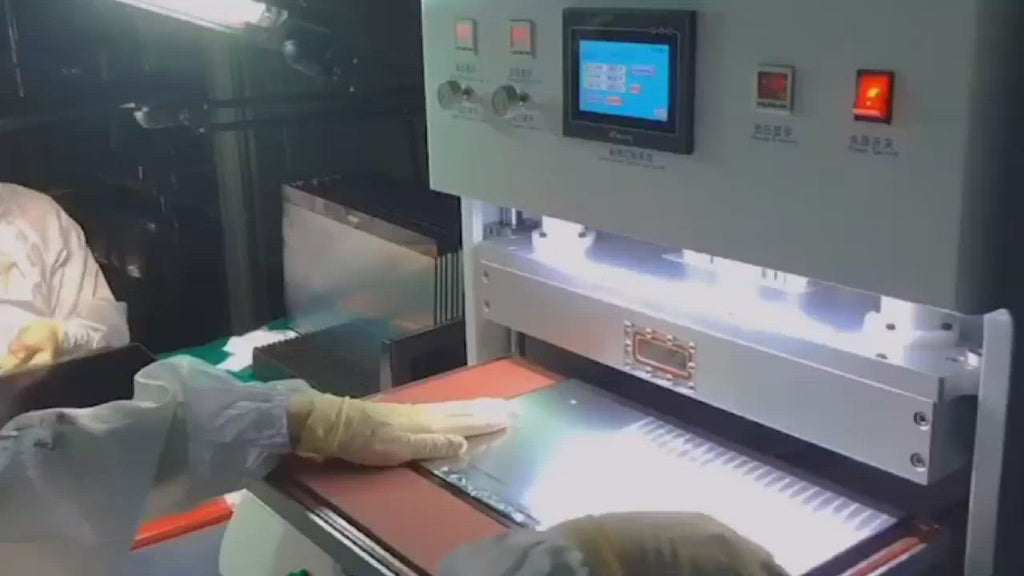
 View CCD Laminating Machine
CCD alignment is useful when touch layers, cover glass borders, and screen edges must stay repeatable across repeated display stack assembly.
What Makes a Display Stack Complex
A complex stack does not always look complex on the table. A panel may only have one cover glass, one LCD, and one adhesive sheet. Still, the problem may appear after lamination because the black border hides bubbles, the glass edge is slightly raised, or the film moves during placement.
The first sign is usually repeat behavior. If the same edge keeps showing bubbles, the cause is often air release or fixture support. If one corner keeps shifting, the cause may be alignment control. If pressure marks appear in the same zone, force may be gathering at one point under the panel.
Therefore, complexity should be judged by behavior, not just layer count. A small curved glass display can be harder than a larger flat panel. A narrow black border can make alignment stricter. A thick cover lens can demand better support before pressure is applied.
Phenomenon: Edge bubbles appear after the panel looked clean
Edge bubbles often appear late. The screen may look fine right after bonding, then a line of tiny bubbles shows near the border after 30 to 60 minutes. This usually means trapped air is moving slowly through the adhesive layer.
The cause is often not “too little pressure.” It may be a blocked air path, uneven glass edge, thick black border, or weak fixture support. Raising pressure without checking these details can create pressure marks while the bubble problem remains.
A practical judgment method is simple. Mark bubble positions on five samples. If bubbles gather near one side, inspect fixture support and glass flatness. If they appear around the full border, review adhesive placement, release direction, and debubble timing.
Phenomenon: Alignment shifts during bonding
Alignment shift can happen before anyone notices. A film may slide when the adhesive touches down. A touch sensor may move when the chamber closes. A panel may drift because the fixture does not lock the edge firmly enough.
The judgment should happen in two steps. First, check alignment before chamber closure. Then check again after bonding. If the offset appears only after closure, the process may need CCD alignment, a better fixture stop, or slower placement.
This is where a Multi-Layer Screen Bonder becomes part of the decision. The point is not to add complexity. The point is to make repeated stack assembly easier to control.
Layer Order and Adhesive Choice
Layer order should be confirmed before the first trial. A simple note is enough: cover glass, OCA, touch sensor, OCA, LCD, protective film. This drawing shows where air may stay, where dust can enter, and where alignment must be checked.
OCA is usually cleaner for flat, repeatable structures. It has a fixed thickness and a clear film handling process. However, it can struggle when a cover lens has curved edges, stepped borders, or uneven gaps.
OCR can fill some irregular spaces because it flows before curing. However, it brings another set of questions. How will resin flow near the cable side? How will overflow be controlled? How will the curing step affect the stack?
The better choice comes from the shape. Flat panels often fit OCA well. Curved glass or uneven structures may need OCR testing. Protective film work needs a different rhythm because dust, tension, and surface scratches become more visible.
 View Film Lamination Machine
Industrial display film lamination is useful when protective film, anti-glare film, or HMI surface protection needs clean and stable handling.
Pressure Control: More Force Is Not Always Better
Pressure is often misunderstood. More pressure may flatten a bubble, but it can also create stress marks, light leakage, or corner distortion. In multi-layer bonding, pressure should follow the weakest layer, not the strongest glass.
The reason is easy to see. A touch sensor, polarizer, or thin LCD module may not accept the same force as cover glass. If the fixture is uneven, pressure gathers at the high point. The result may be a mark in the center or haze near a support area.
The judgment method should stay hands-on. Place the panel on the fixture for 10 seconds before bonding. Look at side reflections. If one edge sits higher, pressure will probably travel unevenly. At that moment, fixture correction is more useful than changing machine settings.
Curved glass needs controlled contact
Curved glass behaves differently from flat glass. The center may touch first, while the edges need time to settle. If pressure comes too fast, adhesive may move unevenly near the bend.
Therefore, curved display bonding needs gradual pressure, controlled release, and careful edge inspection. A custom fixture may matter more than a larger machine. The fixture should support the glass shape instead of forcing it flat.
Large panels need handling space, not only chamber size
A larger working area helps when panel loading becomes risky. For example, large cover glass may flex while being moved. Two operators may need extra space to place the screen without touching the active area.
However, a larger platform will not fix dust or poor peeling habits. If the adhesive surface stays open too long, particles can still enter the stack. Bigger equipment should support a cleaner workflow, not hide an unstable one.
 View OCA Vacuum Laminator
OCA vacuum lamination works better when film peeling, panel support, alignment, and air release are planned as one process.
Inspection Checklist for Multi-Layer Bonding
Inspection should not wait until the final display test. By then, the stack is already sealed, and the cause becomes harder to find. A better routine checks the panel at small points before the next layer covers the problem.
Overhead light catches obvious dust. Side light reveals edge bubbles, wrinkles, haze, and pressure marks. A dark-screen test can show particles and uneven optical areas. Using the same light angle every time makes the defect record much more useful.
Practical Pre-Production Checklist
- Draw the stack order from top to bottom before choosing the process.
- Check panel size, active area, black border width, and cover glass thickness.
- Confirm whether the stack uses OCA, OCR, SCA, PET, AG, AR, AF, or EMI film.
- Inspect each layer under side light before removing the release liner.
- Check where air can escape near edges, curves, and stepped borders.
- Place the panel on the fixture and check whether one side sits higher.
- Record pressure, time, waiting period, and debubble settings for every sample group.
- Take one full-panel photo and one close-up defect photo under the same light.
- Change only one process variable at a time during testing.
Dust control is mostly about movement
Dust usually enters during handling. The film may be peeled too early. A glove may touch the adhesive edge. A table may hold old residue from the previous panel. These details sound small, but they decide whether a black dot appears after bonding.
The best method is to reduce open-air time. Peel the release liner close to the bonding moment. Keep the peeling direction consistent. Separate cleaning tools for glass, fixtures, and outer surfaces. These habits are not exciting, but they work.
Bubble mapping is better than guessing
When bubbles repeat, do not guess. Draw the panel outline on paper and mark each bubble position after inspection. After five samples, the pattern becomes clearer.
If bubbles stay near one corner, look at fixture support and air path. If bubbles appear late around the border, bubble removal may need to become part of the planned workflow. This is more reliable than raising pressure again and again.
 View Bubble Removal Machine
Bubble removal is useful when trapped air appears after OCA, SCA, thick glass, or larger display stack bonding.
How to Match a Suitable Setup with Jiutu
A useful setup discussion should start with samples and defects. A short stack drawing, two defect photos, and the current process steps are more helpful than a long machine request. The stack tells what should happen. The defect photo shows what actually happened.
A good message can be simple. For example: 15.6-inch flat cover glass, OCA, touch sensor, LCD. Edge bubbles appear on the right side after 40 minutes. Manual alignment shifts near the lower corner. This gives enough clues to discuss working area, fixture support, CCD alignment, and bubble removal.
Another example may involve curved glass. Curved cover lens, OCR under testing, stress marks near the bend, and small resin overflow near the cable side. In that case, the discussion should focus on resin flow, fixture shape, pressure release, and curing control.
For this reason, Jiutu setup matching should include panel size, glass thickness, adhesive type, daily quantity, stack order, fixture photos, and defect photos. The right direction may involve vacuum lamination, CCD alignment, film lamination, custom fixture support, or bubble removal.
Suitable Scenarios for Multi-Layer Display Stack Assembly
Multi-layer bonding is suitable for industrial computer screens, HMI panels, automotive displays, rugged screens, medical displays, outdoor control panels, and repair/refurbishment work. These screens often need more than a simple glass-to-LCD bond.
Industrial computer displays often need surface protection and glare control. A factory screen may face gloves, dust, oil mist, and strong overhead light. In this case, AG, AF, AR, or PET film may become part of the stack.
Automotive displays need more attention to alignment and curved glass stress. A dashboard frame does not hide small mistakes. Even a slight corner offset can look obvious after installation.
Repair rooms need steady refurbishment results. The target is a clean screen with fewer bubbles, less dust, and fewer pressure marks. In that setting, fixture repeatability and inspection discipline may matter more than speed.
Experience Tips That Improve Real Bonding Results
First, do not peel film too early. Once the release liner is removed, the adhesive surface begins to collect dust and static. Even one or two minutes can matter in a busy repair room.
Second, keep the peeling direction consistent. If every operator peels in a different direction, dust patterns and alignment behavior may change between batches. A fixed method makes troubleshooting easier.
Also, inspect under side light. Ceiling light can miss fine bubbles and faint pressure marks. A small lamp at the same angle gives a more honest view of the stack.
Finally, change one variable at a time. If pressure, adhesive, fixture, and waiting time all change together, the result becomes hard to read. One change per sample group creates better evidence.
FAQ: Multi-Layer Screen Bonder and Display Stack Assembly
When is a Multi-Layer Screen Bonder needed?
A Multi-Layer Screen Bonder is useful when the display stack includes several adhesive interfaces, touch layers, protective films, curved glass, or repeated alignment problems. It is also worth discussing when edge bubbles, pressure marks, or delayed trapped air keep appearing after ordinary lamination.
How should OCA and OCR be judged?
OCA is usually cleaner for flat and repeatable screen structures. OCR can help with curved glass, uneven gaps, or stepped edges. However, OCR needs better control of flow, overflow, and curing. The panel shape should guide the first decision.
Does every layered display need CCD alignment?
No. CCD alignment is most useful when the visible border is narrow, the touch sensor has strict reference points, or manual placement keeps drifting. If several samples show different corner offsets, CCD alignment should be reviewed.
Why do bubbles appear later instead of right after bonding?
Delayed bubbles usually mean trapped air is moving slowly through the adhesive layer. Thick glass, black borders, uneven pressure, and blocked air paths can cause this. A debubble step or fixture adjustment may help more than simply raising pressure.
What details should be prepared before setup matching?
Prepare panel size, cover glass thickness, stack order, adhesive type, daily quantity, fixture photos, and defect photos under side light. These details help Jiutu match a suitable bonding direction based on real screen behavior.
Next Step: Match the Stack Before Choosing the Machine
Multi-layer bonding becomes easier when the process is treated as a chain of small judgments. The visible defect is only the last signal. Before that, layer order, adhesive behavior, pressure path, fixture support, dust control, and inspection timing have already shaped the result.
A Multi-Layer Screen Bonder should help control that chain with cleaner alignment, steadier pressure, better air release, and repeatable handling. For OCA, OCR, protective films, curved glass, edge bubbles, or alignment drift, the best next step is sample-based setup matching.
- Prepare panel size, glass thickness, adhesive type, daily quantity, and stack order.
- Take defect photos under side light, including one full-panel photo and one close-up photo.
- Ask Jiutu to match the suitable setup based on real samples, fixture needs, and defect behavior.