Within display-module repair, the term LED bonding machine refers to module-level bonding equipment used for FPC, FFC, COF-related contact repair, ACF film work, touch panel assembly, and optical bonding support. This article does not cover finished LED display walls, advertising cabinets, or complete screen installation projects.
This article focuses on the practical factors that affect display-module repair quality: alignment, pressure, adhesive layers, fixture support, inspection steps, and equipment selection. The goal is to help repair labs, refurbishment teams, and display-module assembly teams identify the most suitable Jiutu equipment category before requesting a quotation.
Module Bonding Use Cases
The first step is to define the application correctly. A module-level bonding process usually handles one controlled connection area or one defined optical stack. For example, the task may involve a lifted flexible cable, weak FPC contact, FFC connection, COF-related fault, touch panel layer, cover glass layer, or ACF film bonding point.
This differs from producing or installing complete LED display systems. Finished display projects involve cabinets, control cards, power distribution, brightness planning, weather protection, and installation work. Module bonding works on a smaller area, but it often requires tighter control of position, pressure, temperature, time, and adhesive behavior.
In practical repair workflows, common applications include FPC bonding, FFC bonding, COF inspection support, chip contact bonding, ACF hot press bonding, optical contact bonding, touch panel bonding, and small display module sample assembly. Therefore, the equipment should match the process step, not only the machine name.
Cable contact repair
Suitable for FPC, FFC, COF-related, chip, and connector areas where electrical contact depends on clean alignment and stable compression.
Optical layer bonding
Suitable for touch panel, cover glass, LCD module, OCA, SCA, and TP+LCM work where bubbles, haze, and edge lift must be controlled.
Sample assembly
Suitable for display module trial bonding before stable repair, refurbishment, or small-batch assembly routines are defined.
Display Module Repair and Assembly
The repair route should begin with fault isolation. A display module may fail because of poor cable contact, damaged pads, weak ACF bonding, optical bubbles, dust, touch layer shift, or panel damage. Because each fault points to a different process, diagnosis should happen before equipment selection.
For instance, vertical lines after screen separation may indicate a flex cable or COF-related contact issue. A clear image with unstable touch response may suggest a touch layer, flex tail, or connector problem. Visible bubbles or haze after lamination usually point to the optical bonding or bubble-removal workflow rather than cable repair.
Therefore, module-level work benefits from a clear process map. A typical path may include cleaning, inspection, pre-test, fixture setup, alignment, bonding, cooling, electrical test, optical test, and final inspection. When this sequence stays stable, repair teams can improve yield without changing random settings from one screen to the next.
Scope note for this application
This guide focuses on phone, tablet, LCD, OLED, touch panel, HMI, automotive display, and industrial display module bonding. It does not cover finished LED cabinet sales, outdoor billboard installation, or complete video wall engineering.
Alignment and Pressure Requirements
Alignment comes before pressure. Even a small positional offset can create missing lines, weak touch response, or an unstable signal. For this reason, fine-pitch display-module bonding often requires a stable platform, magnified viewing, clean lighting, and a fixture that prevents movement during the bonding cycle.
At the same time, pressure must stay even. Low pressure can leave incomplete contact or poor adhesive activation. Excessive pressure can damage pads, mark films, bend thin glass, or stress a display edge. Therefore, the correct range depends on machine model, cable structure, adhesive type, part thickness, and bonding area.
Temperature also requires careful control. Jiutu’s ACF-related machines use pulse heating with an ACF adhesive process for chips, FPC, and FFC cables. The ACF Bonding Machine product page lists a machine range of 0–500°C, but this is an equipment capability range rather than a universal operating setting. The correct process window depends on the machine model, adhesive film, cable material, part structure, and sample-test results.
| Control Point | Why It Matters | Practical Check |
|---|---|---|
| Alignment | Prevents contact shift, line defects, weak touch response, and unstable signal. | Use fixture support, camera view, and pre-bond positioning checks. |
| Pressure | Controls contact quality, adhesive activation, and bonding uniformity. | Confirm by sample material, bonding area, fixture support, and machine specification. |
| Temperature | Affects ACF activation, cable stress, and nearby display layers. | Start from material guidance, then verify with scrap or sample modules. |
| Time | Too short may fail bonding; too long may overheat sensitive parts. | Record time together with temperature, pressure, cooling, and test result. |
Materials Used in Module Bonding
Material choice shapes the machine path. ACF means Anisotropic Conductive Film. It creates vertical electrical connection when heat and pressure activate conductive particles inside the film. Because of that structure, ACF work fits FPC, FFC, chip, connector, and contact bonding tasks.
OCA means Optically Clear Adhesive. It is a transparent film used between optical layers, such as cover glass, touch panel, and LCD module. In contrast to ACF, OCA work focuses on clarity, bubble control, edge stability, and visual uniformity.
Some larger or specialized display assemblies use SCA or LOCA-based optical bonding. These processes require controlled dispensing volume, flow, curing, masking, and overflow prevention. For additional optical-bonding context, Henkel explains how liquid optically clear adhesives can bond protective cover lenses to displays in plastic-to-glass and glass-to-glass structures.
In addition, auxiliary materials matter. Cleaning cloth, dust removal film, release liner, high-temperature tape, protective film, fixture padding, and silicone pads all affect the result. A poor consumable can damage a good module, so process quality often depends on small items that never appear in the machine name.
ACF film
Best for electrical contact bonding on FPC, FFC, chips, and display panel connector areas.
OCA film
Best for transparent optical layer bonding where bubbles, dust, haze, and edge lift must be controlled.
Fixture materials
Best for keeping glass, module edges, flex tails, and bonding areas stable during pressure and heat.
Which Equipment Fits Which Module Task?
A good equipment decision starts with the fault location. If the problem sits around a flex cable, connector, chip, FPC, FFC, or COF edge, local electrical bonding should be reviewed first. However, if the defect sits between transparent layers, optical bonding, lamination, and bubble control equipment should be reviewed first.
The table below gives a simple selection path before looking at individual machines. It helps connect the repair symptom with the most relevant Jiutu equipment direction.
| Module Task | Better Equipment Direction | Best-Fit Project Type |
|---|---|---|
| FPC, FFC, chip, or connector bonding | ACF bonding machine or pulse hot press equipment | Phone screen repair, tablet display repair, flex cable recovery, connector repair |
| COF-related line fault inspection and repair support | Pulse heat press machine with accurate local pressure control | LCD line fault recovery, flex contact work, narrow edge bonding |
| TP+LCM optical bonding | TP+LCM vacuum bonding machine or OCA laminating equipment | Touch panel assembly, LCD module bonding, display refurbishing workflow |
| Cover glass, OCA, or wide optical layer bonding | CG+OCA vacuum bonding or optical bonding equipment | Cover glass replacement, optical clarity improvement, bubble-free lamination |
| Post-lamination micro-bubbles | Bubble remover or autoclave-style pressure equipment | OCA lamination finishing, screen refurbishing, optical bonding yield control |
Recommended Jiutu Equipment
For module-level bonding decisions, the Optical Bonding Machine category is the most relevant starting point. It gathers hot press, ACF/FPC, optical contact, and bonding-related equipment in one area. As a result, the page helps separate cable bonding needs from optical bonding needs.
In addition, the LCD Repair Machine category is useful when the workflow includes OCA lamination, vacuum bonding, TP+LCM work, CG+OCA work, and wider screen refurbishment equipment. Therefore, both categories can support different steps inside one repair bench or assembly line.
The equipment below is not a one-size-fits-all list. Instead, each option represents a different process direction. Final selection should be based on display size, cable area, adhesive type, pressure needs, voltage, output volume, and project photos.

Best for FPC / FFC / chip contact bonding
ACF Bonding Machine
A practical fit for ACF film work involving FPC, FFC, chips, and display panel contact areas. This direction is useful when electrical contact depends on heat, pressure, and precise pad alignment.
View Specifications / Ask Availability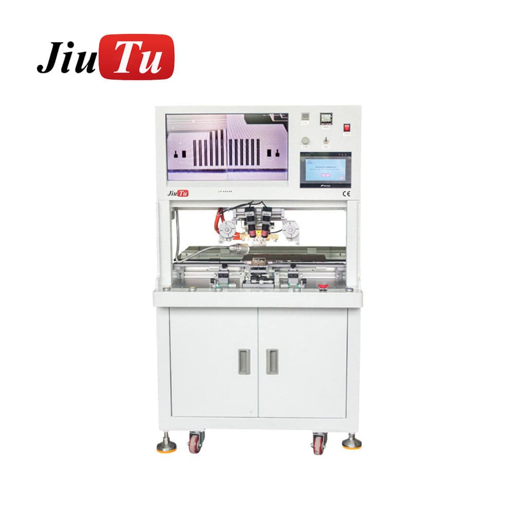
Best for flex cable and COF-related repair
LCD Pulse Heat Press Machine
A better direction for flex cable and COF-related LCD repair tasks where fast pulse heating helps reduce unnecessary heat exposure around nearby display layers.
View Specifications / Ask Availability
Best for TP+LCM optical bonding
TP+LCM Vacuum Bonding Machine
A suitable path for bonding touch panels directly to LCD modules using OCA adhesive under vacuum pressure, especially when optical quality and bubble control matter.
View Specifications / Ask AvailabilityProcess Limits to Confirm Before Purchase
Even with the correct bonding equipment, some modules cannot be recovered. For example, missing pads, burned IC areas, cracked traces, heavy corrosion, and broken glass layers may not respond to pressure or heat. Therefore, incoming inspection should separate repairable faults from scrap-level damage.
Moreover, optical defects do not always come from the bubble removal step. Dust, poor cleaning, wrong OCA size, uneven support, or weak vacuum can create defects that appear later. In that case, adding more pressure after lamination may not solve the real root cause.
For that reason, equipment planning should include upstream and downstream checks. Cleaning tools, fixtures, molds, inspection lights, display testers, alignment cameras, and process records often decide whether the machine performs well in daily work.
Factory Support and Workflow Planning
A useful support conversation should begin with the module, not the catalog. The same visible defect can come from weak cable bonding, poor ACF activation, unsuitable fixture support, optical dust, or an unstable lamination step. Therefore, fault photos and part structure often shorten the selection process.
JiutuStore focuses on phone repair tools and LCD repair equipment, allowing a workflow to connect bonding, lamination, bubble removal, polishing, and related screen-refurbishment steps. In mixed workflows, that matters. A module may need cable bonding first, then optical lamination, then bubble removal and final testing.
In addition, factory discussion helps confirm whether standard equipment is enough. A curved automotive display, thick cover glass, unusual cable direction, wide HMI panel, or custom touch module may need customized fixture support. Early confirmation reduces the risk of choosing a machine that looks correct but does not fit the real part.
Project Details to Prepare Before Inquiry
Before requesting a machine recommendation, the project details should be clear enough for process matching. A short message with real module information is more useful than a general machine name. In many cases, photos and measurements help confirm the equipment direction faster than a long description.
The following details are especially useful for display module repair, bonding, and assembly projects:
Module size
Overall size, active area, thickness, glass shape, and cable exit direction.
Application environment
Phone, tablet, HMI, automotive display, medical device, POS terminal, or industrial panel.
Production volume
Sample work, small repair batches, expected daily output, or repeated assembly demand.
Country and voltage
Destination country, power supply requirement, plug preference, and shipping needs.
Installation method
Flat bonding, fixture holding, vacuum platform, cable holder, mold, or special support method.
Photos or videos
Close-up photos of the fault, cable area, pad area, adhesive layer, and current equipment.
Inquiry message checklist
A complete inquiry can include module size, fault type, adhesive layer, expected quantity, country, voltage, project photos, and equipment already in use.
Contact Jiutu for Equipment MatchingExtended Reading and Related Resources
The resources below connect this topic with optical bonding, COF troubleshooting, ACF process selection, and wider LCD repair workflows.
FAQ
Is this equipment used for finished LED display screen production?
No. This article focuses on display module repair and assembly. Finished display screen production involves cabinet design, power supply, controller systems, brightness planning, and installation engineering. Module bonding focuses on cable contact, adhesive layers, alignment, pressure, and inspection.
What is the difference between ACF bonding and optical bonding?
ACF bonding is mainly for electrical connection. It uses conductive film between pads, cables, chips, or connectors. Optical bonding is mainly for transparent layer joining, such as cover glass, touch panel, OCA film, and LCD module bonding. Therefore, the inspection method is different.
When does a display module need pulse heat press bonding?
Pulse heat press bonding is useful when a local cable, contact, or COF-related area needs fast heating and controlled pressure. It can reduce unnecessary heat exposure around nearby parts. However, exact suitability depends on the module, cable, adhesive film, and machine model.
Can one machine handle FPC bonding, OCA lamination, and bubble removal?
Usually not. FPC bonding, OCA lamination, and bubble removal use different mechanisms. Cable bonding needs local alignment and pressure. OCA lamination needs surface control and vacuum support. Bubble removal needs post-lamination pressure and time control.
What information helps Jiutu recommend the right display module bonding setup?
Helpful information includes display size, cable width, pad photos, adhesive type, fault photos, application environment, expected quantity, country, voltage, installation method, and current equipment. Photos or short videos often make the process matching much faster.
Conclusion: Choose by Process, Not by Machine Name
Display module bonding depends on the real fault location. Cable contact work, ACF film bonding, optical layer bonding, and bubble removal all need different controls. Therefore, the safest selection path starts with the module structure, repair goal, adhesive layer, fixture requirement, and test method.
When evaluating an LED bonding machine for a repair bench or display-module assembly project, provide real module photos, dimensions, expected quantity, voltage, destination country, and current workflow details. This makes equipment matching clearer and reduces avoidable mistakes before quotation.
- First, identify whether the fault is electrical contact, optical layer adhesion, or post-lamination bubbles.
- Second, prepare module size, adhesive type, cable photos, project quantity, country, and voltage details.
- Finally, contact Jiutu with photos and workflow notes before final equipment selection.